このページは機械翻訳を使用して翻訳されました。最新版の英語を参照するには、ここをクリックします。
NB-IoT NTN NPDSCHスループット
この例では、非地上ネットワーク ( NTN)チャネルで狭帯域モノのインターネット (NB-IoT) 狭帯域物理ダウンリンク共有チャネル(NPDSCH) スループットをシミュレートする方法を示します。この例では、欧州電気通信標準化機構 ( ETSI) ライス フェーディングチャネルと国際電気通信連合無線通信部門 (ITU-R) P.681陸上移動衛星(LMS)チャネルの 2 つの狭帯域NTNチャネルがサポートされています。
はじめに
この例では、3GPP NB-IoT規格[3]、[4]、[5]、[6]、[7]で定義されているNB-IoTリンクのNPDSCHスループットを測定します。
この例ではこれらの機能をモデル化しています。
トランスチャネル符号化
NPDSCH、狭帯域参照信号(NRS)、および同期信号(狭帯域プライマリ同期信号NPSS、狭帯域セカンダリ同期信号NSSS)
ETSIライスチャネルおよびITU-R P.681 LMSチャネル
単一入力単一出力(SISO)リンク
送信機でのドップラー事前補償と受信機でのドップラー補償
オプションのパワーアンプモデリング
図は実装された処理チェーンを示しています。わかりやすくするために、図には NRS 信号と同期信号は示されていません。

NB-IoT NPDSCH 送信機および受信機処理ユニットの詳細については、NB-IoT NPDSCH Block Error Rate Simulation (LTE Toolbox) の例を参照してください。
シミュレーションの合計時間を短縮するには、Parallel Computing Toolbox ™ を使用して、送信電力ループの送信電力値の範囲を並列に実行できます。
シミュレーションの長さ、送信機、受信機を構成する
シミュレーションの長さをトランスポート ブロックの数で設定します。この例ではデフォルトで 10 個のトランスポート ブロックが使用されていますが、意味のあるスループット結果を生成するには、多数のトランスポート ブロックを使用する必要があります。シミュレートする送信電力値の範囲を設定します。送信電力は、ドップラー事前補償を実行する前の時間領域波形の電力として定義され、電力増幅器のゲインが含まれます。受信機にはノイズ指数とアンテナ温度が含まれます。ノイズ指数は受信機の内部ノイズをモデル化し、アンテナ温度は入力ノイズをモデル化します。この受信機はアンテナ要素ごとのノイズを指定します。この例では、異なる繰り返し値でシミュレーションを実行し、繰り返しによるパフォーマンスの向上を比較します。iReps 変数は、NPDSCH がスケジューリング情報ブロック SIB1-NB を伝送しない場合にのみ適用されます。
numTrBlks = 10;             % Number of simulated transport blocks
iReps = [0 5];              % Range of repetitions simulated
txPower = 30:5:45;          % Transmit power (dBm)
rxNoiseFigure = 6;          % Noise figure (dB)
rxAntennaTemperature = 290; % Antenna temperature (K)
パワーアンプの構成
メモリレス電力増幅器の非線形性を構成するには、enablePA を使用します。TR 38.803 の付録 A に定義されているパワー アンプ モデルのいずれかを選択できます。
2.1 GHz ガリウムヒ素 (GaAs)
2.1 GHz 窒化ガリウム (GaN)
あるいは、paModel を Custom に設定し、paCharacteristics を使用して 3 列のマトリックスでパワー アンプの特性を定義することもできます。最初の列は入力電力を dBm 単位で定義します。2 番目の列は出力電力を dBm 単位で定義します。3 番目の列は出力位相を度単位で定義します。paCharacteristics 変数が空に設定され、paModel が Custom に設定されている場合、この例では 2.1 GHz の横方向拡散金属酸化膜半導体 (LDMOS) Doherty ベースの増幅器が使用されます。
波形に適用されるメモリレス非線形性は、パワーアンプの場合、この式に従います (カスタム構成を除く)。
この式では、
は出力信号です。
は入力信号です。
は多項式の次数の集合です。
は多項式の係数です。
デフォルトでは、この例では enablePA が false に設定されます。
enablePA =false; % true or false paModel =
"2.1GHz GaAs"; % "2.1GHz GaAs", "2.1GHz GaN", or "Custom" paCharacteristics = []; % Lookup table as empty or a matrix with columns: Pin (dBm) | Pout (dBm) | Phase (degrees)
enablePA を true に設定すると、scaleFactor 変数を使用して最大入力信号振幅を変更し、パワー アンプの非線形性を励起します。scaleFactor は、パワーアンプの動作領域を制御し、各送信アンテナで信号振幅のスケーリングを適用します。scaleFactor 変数を使用して電力バックオフを設定することもできます。たとえば、パワー アンプを通過する信号に 3dB のパワー バックオフを提供するには、scaleFactor を -3 に設定します。入力信号がパワーアンプモデルの特性範囲内であることを確認します。
scaleFactor と paCharacteristics の両方が空に設定され、paModel が Custom に設定されている場合、例ではデフォルト値 -35 dB が使用されます。それ以外の場合、scaleFactor が空に設定されている場合、例ではデフォルト値の 0 dB が使用されます。
scaleFactor = []; % Amplitude scaling, in dB

% If enablePA is set to true, visualize the power amplifier gain and phase
% characteristics
paModelImpl = paModel;
paInputScaleFactor = 0;                                 % in dB
if enablePA == 1
    % Set the power amplifier as applicable for the further processing
    if lower(paModel) == "custom"
        if isempty(paCharacteristics)
            tableLookup = getDefaultCustomPA;
            paInputScaleFactor = -35;
        else
            tableLookup = paCharacteristics;
        end
        % Use table look-up option of comm.MemorylessNonlinearity and provide
        % the power amplifier characteristics
        mnl = comm.MemorylessNonlinearity(Method="Lookup table", ...
            Table=tableLookup);
        plot(mnl)
        paModelImpl = mnl;
    else
        paMemorylessNonlinearity(paModel)
    end
end
% Update the power amplifier input scaling factor, based on scaleFactor
if ~isempty(scaleFactor)
    paInputScaleFactor = scaleFactor;
end
ドップラー補正構成
この例では、送信側と受信側の 2 つのドップラー補正構成がサポートされています。送信側での補正には、txDopplerCompensator を有効にします。txDopplerCompensator 変数を true に設定すると、衛星の動きによって発生するドップラーに対して送信波形が事前に補正されます。この例では、ドップラー事前補正を実行するときに、衛星の動きによるドップラー効果が既知であると想定しています。受信側で補正するには、rxDopplerCompensator を有効にします。rxDopplerCompensator 変数を true に設定すると、受信機は NPSS を使用してドップラー補正を実行します。送信電力が低い場合、受信機でのドップラー推定が不正確になり、動作信号対雑音比が -10 dB 未満になる可能性があることに注意することが重要です。
txDopplerCompensator =true; % true or false rxDopplerCompensator =
false; % true or false
上位レイヤーパラメーターの設定
eNodeB および NPDSCHパラメーターを構成するには、これらの上位レイヤーパラメーターを設定します。
npdschDataType ="NotBCCH"; % "SIB1NB", "BCCHNotSIB1NB", or "NotBCCH" iSF = 0; % Resource assignment field in DCI (DCI format N1 or N2) schedulingInfoSIB1 = 0; % Scheduling information field in MasterInformationBlock-NB (MIB-NB) iMCS = 4; % Modulation and coding scheme field in DCI (DCI format N1 or N2)
eNodeBとNPDSCHの構成
これらの eNodeBパラメーターを設定します。
NB-IoT物理レイヤーセルID
操作モード
enb = struct; enb.NNCellID = 0; % NB-IoT physical layer cell identity enb.OperationMode ="Standalone"; % "Standalone", "Guardband", "Inband-SamePCI", or "Inband-DifferentPCI"
NPDSCH 構造に無線ネットワークの一時識別子を設定します。
npdsch = struct;
npdsch.RNTI = 1; % Radio network temporary identifier
伝播チャネルモデルの構成
シミュレーション用のチャネルモデル オブジェクトを作成します。この例では、 ETSI RicianチャネルとITU-R P.681 LMSチャネルがサポートされています。これらのチャネルからNTNチャネルを取得するには、追加のドップラー シフトを適用します。この式を使用して、TR 38.811 に指定されている衛星の移動によるドップラーシフトを計算します。
この式では、
は衛星の速度です。
は光の速度です。
は地球の半径です。
は衛星の高度です。
は衛星の仰角です。
は搬送周波数です。
デフォルトでは、この例では、搬送周波数が 2 GHz で、高度600 km の低軌道にある衛星を想定しています。NB-IoT ユーザー機器 (UE) は時速 3 km の速度で移動しています。また、この例では、衛星が円軌道上を移動することを想定しています。
channel = struct; channel.NTNChannelType ="ETSI Rician"; % "ETSI Rician" or "ITU-R P.681" channel.CarrierFrequency = 2e9; % Carrier frequency (in Hz) channel.ElevationAngle = 50; % Elevation angle (in degrees) channel.MobileSpeed = 3*1000/3600; % UE speed (in m/s) channel.MobileAltitude = 0; % Mobile altitude (in m) channel.SatelliteAltitude = 600e3; % Satellite altitude (in m) channel.Seed = 73; % Random seed channel.IncludeFreeSpacePathLoss =
true; % Include or exclude free space path loss % Set these fields based on the type of channel selected if lower(channel.NTNChannelType) == "etsi rician" % For ETSI Rician channel, set KFactor channel.KFactor = 10; % In dB else % For ITU-R P.681, set Environment and AzimuthOrientation channel.Environment = "Urban"; % "Urban", "Suburban", "RuralWooded", or "Residential" channel.AzimuthOrientation = 0; % In degrees end
チャネル推定器の構成
cec 構造を使用して実用的なチャネル推定器を構成します。デフォルトでは、この例ではこれらの仕様でチャネルが構成されます。
搬送周波数 — 2 GHz
NB-IoT UEの速度 — 3 km/h
この構成では、ドップラー拡散は 5.5 Hz になります。したがって、これらの設定を使用してパイロット推定値の周波数平均を実行します。
時間ウィンドウ - 1 つのリソース要素 (RE)
周波数ウィンドウ - 25 RE、リソースブロックのすべてのサブキャリアの平均化を保証する
% Configure channel estimator
cec.PilotAverage = "UserDefined";   % Type of pilot symbol averaging
cec.TimeWindow = 1;                 % Time window size in REs
cec.FreqWindow = 25;                % Frequency window size in REs
cec.InterpType = "Cubic";           % 2-D interpolation type
cec.InterpWindow = "Centered";      % Interpolation window type
cec.InterpWinSize = 3;              % Interpolation window size
cec.Reference = "NRS";              % Channel estimator reference signal
処理ループ
各繰り返しインデックスと送信電力インデックスでのスループットを決定するには、次の手順に従います。
トランスポート ブロックを生成します — 設定された上位レイヤーパラメーターに応じてトランスポート ブロックのサイズを取得します。
リソース グリッドを生成する — 変調ビット、NPSS、NSSS、NRS 信号をリソース グリッドにマップします。
lteNDLSCH(LTE Toolbox) 関数は、入力トランスポート ブロックに対してトランスポートチャネルコーディングを実行します。次に、lteNPDSCH(LTE Toolbox) 関数がエンコードされたデータ ビットを変調します。波形の生成 —
lteSCFDMAModulate(LTE Toolbox) 関数を使用して、サブキャリアを半分シフトした NB-IoT 時間領域 OFDM 波形を生成します。パワー アンプの非線形性を適用する — ベースバンド OFDM 信号にメモリレス非線形性を適用します。
ドップラー事前補正を適用する — 生成された波形に衛星の移動によるドップラーシフトを適用し、チャネルによって誘発される衛星ドップラーシフトを事前補正します。
ノイズの多いチャネルをモデル化して適用する — 生成された波形をETSI Rician またはITU-R P.681 LMSフェーディングチャネルに渡して、フェーディングされた波形を取得します。パス ロスを適用し、フェードされた波形に熱ノイズを追加します。
ドップラー補正を適用する — 受信波形のドップラーシフトを推定し、ドップラーシフトを補正します。
同期と OFDM 復調を実行する — 受信した波形を NPSS と相関させることにより、タイミング同期を実行します。次に、
lteSCFDMADemodulate(LTE Toolbox) 関数が同期信号を復調します。チャネル推定を実行する — NRS を使用してチャネルを推定します。
NPDSCH をデコードする —
lteNPDSCHDecode(LTE Toolbox) 関数を使用して、推定されたチャネルとノイズ分散を持つ NPDSCH をデコードします。トランスポート ブロックをデコードする —
lteNDLSCHDecode(LTE Toolbox) 関数を使用してソフト ビットをデコードします。この関数は、コードワード データをデコードし、ブロック巡回冗長検査 (CRC) エラーを返します。
% Use the higher layer parameters, and check if the provided configuration
% is valid
numRep = numel(iReps);
npdschInfo = hNPDSCHInfo;
npdschInfo.NPDSCHDataType = npdschDataType;
npdschInfo.ISF = iSF;
npdschDataTypeLower = lower(npdschDataType);
if npdschDataTypeLower == "sib1nb"  % NPDSCH carrying SIB1-NB
    npdschInfo.SchedulingInfoSIB1 = schedulingInfoSIB1;
    % Store a copy of the information structure for all the repetitions
    npdschInfo = repmat(npdschInfo,numRep,1);
else % NPDSCH not carrying SIB1-NB
    npdschInfo.IMCS = iMCS;              % Modulation and coding scheme field in DCI (DCI format N1 or N2)
    % Store a copy of the information structure for all the repetitions
    npdschInfo = repmat(npdschInfo,numRep,1);
    for repIdx = 1:numRep
        npdschInfo(repIdx).IRep = iReps(repIdx); % Repetition number field in DCI (DCI format N1 or N2)
    end
end

% Initialize some parameters of enb
enb.NFrame = 0;
enb.NSubframe = 0;
enb.NBRefP = 1;
opMode = lower(enb.OperationMode);
inbandSamePCI = (opMode == "inband-samepci");
inbandDifferentPCI = (opMode == "inband-differentpci");
if inbandSamePCI
    enb.CellRefP = enb.NBRefP;     % Number of cell RS antenna ports (Fixed to 1 in this example)
    enb.NCellID = enb.NNCellID;
elseif inbandDifferentPCI
    enb.CellRefP = enb.NBRefP;     % Number of cell RS antenna ports (Fixed to 1 in this example)
    enb.NCellID = 1;
end
if ((npdschDataTypeLower == "bccnnotsib1nb") || (npdschDataType == "notbcch")) && ...
        (inbandSamePCI || inbandDifferentPCI)
    enb.ControlRegionSize = 3;     % The allowed values are 0...13
end

% Apply default window size according to TS 36.104 Table E.5.1-1a
if(~isfield(enb,"Windowing"))
    enb.Windowing = 6;
end

% Store enb structure with a name used for OFDM modulation and
% demodulation. The NB-IoT downlink waveform is a 1/2 subcarrier shift
% waveform. The lteSCFDMAModulate and lteSCFDMADemodulate functions use the
% NBULSubcarrierSpacing field to modulate and demodulate the NB-IoT
% downlink waveform, respectively.
enbOFDM = enb;
enbOFDM.NBULSubcarrierSpacing = "15kHz";

% Get the waveform information and set up the NTN channel
waveformInfo = lteSCFDMAInfo(enbOFDM);
ntnChannel = setupNTNChannel(channel,waveformInfo.SamplingRate);

% Compute the noise amplitude per receive antenna
kBoltz = physconst('Boltzmann');
NF = 10^(rxNoiseFigure/10);
T0 = 290;                                               % Noise temperature at the input (K)
Teq = rxAntennaTemperature + T0*(NF-1);                 % K
N0_ampl = sqrt(kBoltz*waveformInfo.SamplingRate*Teq/2.0);

% Compute path loss based on the elevation angle and satellite altitude
c = physconst("lightspeed");
d = slantRangeCircularOrbit( ...
    channel.ElevationAngle,channel.SatelliteAltitude,channel.MobileAltitude);
lambda = c/channel.CarrierFrequency;
pathLoss = fspl(d,lambda)*double(channel.IncludeFreeSpacePathLoss); % in dB

% Initialize throughput result
numTxPow = numel(txPower);
throughputPercent = zeros(numTxPow,numRep);

% Absolute subframe number at the starting point of the simulation
NSubframe = enb.NFrame*10+enb.NSubframe;

% Loop over repetitions
repVal = zeros(numRep,1);
for repIdx = 1:numRep
    % Add these fields to the npdsch structure
    npdsch.NSF = npdschInfo(repIdx).NSF;
    npdsch.NRep = npdschInfo(repIdx).NRep;
    npdsch.NPDSCHDataType = npdschDataType;
    repVal(repIdx) = npdsch.NRep;

    % Get the bit capacity and transport block length
    [~,info] = lteNPDSCHIndices(enb,npdsch);
    rmoutlen = info.G;                 % Bit length after rate matching (codeword length)
    trblklen = npdschInfo(repIdx).TBS; % Transport block size

    % The temporary variables 'enb_init', 'enbOFDM_init', and
    % 'channel_init' create the temporary variables 'enb', 'enbOFDM', and
    % 'ntnChannel' within the transmit power loop to create independent
    % simulation loops for the 'parfor' loop
    enb_init = enb;
    enbOFDM_init = enbOFDM;
    channel_init = ntnChannel;

    for txPowIdx = 1:numTxPow
    % parfor txPowIdx = 1:numTxPow
    % To enable the use of parallel computing for increased the speed,
    % comment out the 'for' statement and uncomment the 'parfor' statement.
    % This functionality requires the Parallel Computing Toolbox. If you do
    % not have Parallel Computing Toolbox, 'parfor' defaults to the normal
    % 'for' statement.

        % Reset the random number generator so that each transmit power
        % point experiences the same noise realization
        rng(0,"threefry");

        enb = enb_init;                        % Initialize eNodeB configuration
        enbOFDM = enbOFDM_init;                % Initialize eNodeB configuration related to OFDM waveform
        ntnChannel = channel_init;             % Initialize fading channel configuration
        txcw = [];                             % Initialize the transmitted codeword
        numBlkErrors = 0;                      % Number of transport blocks with errors
        estate = [];                           % Initialize NPDSCH encoder state
        dstate = [];                           % Initialize NPDSCH decoder state
        lastOffset = 0;                        % Initialize overall frame timing offset
        offset = 0;                            % Initialize frame timing offset
        subframeGrid = lteNBResourceGrid(enb); % Initialize the subframe grid
        foffsetRS = 0;                         % Initialize frequency offset using reference signal

        N0 = N0_ampl;
        pl_dB = pathLoss;
        subframeIdx = NSubframe;
        numRxTrBlks = 0;
        reset(ntnChannel.BaseChannel);
        reset(ntnChannel.ChannelFilter);
        while (numRxTrBlks < numTrBlks)

            % Set current subframe and frame numbers
            enb.NSubframe = mod(subframeIdx,10);
            enb.NFrame = floor((subframeIdx)/10);

            % Generate the NPSS symbols and indices
            npssSymbols = lteNPSS(enb);
            npssIndices = lteNPSSIndices(enb);
            % Map the symbols to the subframe grid
            subframeGrid(npssIndices) = npssSymbols;

            % Generate the NSSS symbols and indices
            nsssSymbols = lteNSSS(enb);
            nsssIndices = lteNSSSIndices(enb);
            % Map the symbols to the subframe grid
            subframeGrid(nsssIndices) = nsssSymbols;

            % Establish if either NPSS or NSSS is transmitted, and if so,
            % do not transmit NPDSCH in this subframe
            isDataSubframe = isempty(npssSymbols) && isempty(nsssSymbols);

            % Create a new transport block, and encode it when the
            % transmitted codeword is empty. The receiver sets the codeword
            % to empty to signal that all subframes in a bundle have been
            % received (it is also empty before the first transmission)
            if isempty(txcw)
                txTrBlk = randi([0 1],trblklen,1);
                txcw = lteNDLSCH(rmoutlen,txTrBlk);
            end

            if (isDataSubframe)
                % Generate NPDSCH symbols and indices for a subframe
                [txNpdschSymbols,estate] = lteNPDSCH(enb,npdsch,txcw,estate);
                npdschIndices = lteNPDSCHIndices(enb,npdsch);
                % Map the symbols to the subframe grid
                subframeGrid(npdschIndices) = txNpdschSymbols;
                % Generate the NRS symbols and indices
                nrsSymbols = lteNRS(enb);
                nrsIndices = lteNRSIndices(enb);
                % Map the symbols to the subframe grid
                subframeGrid(nrsIndices) = nrsSymbols;
            end

            % Perform OFDM modulation to generate the time domain waveform.
            % Use NB-IoT SC-FDMA to get the 1/2 subcarrier shift on the
            % OFDM modulation.
            txWaveform = lteSCFDMAModulate(enbOFDM,subframeGrid);

            % Normalize the waveform with maximum waveform amplitude
            txWaveform0 = txWaveform./max(abs(txWaveform));

            % Apply power amplifier nonlinearities
            txWaveform1 = paMemorylessNonlinearity(paModelImpl,txWaveform0,...
                db2mag(paInputScaleFactor),enablePA);

            % Scale the waveform power based on the input transmit power
            wavePower = 10*log10(sum(var(txWaveform1)));
            powerScaling = (txPower(txPowIdx)-30)-wavePower;      % In dB
            txWaveform1 = db2mag(powerScaling)*txWaveform1;

            % Pad waveform with 25 samples. This covers the range of
            % delays expected from channel modeling (a combination of
            % implementation delay and channel delay spread)
            txWaveform1 = [txWaveform1; zeros(25,enb.NBRefP)]; %#ok<AGROW>

            % Apply Doppler pre-compensation
            txWaveform2 = compensateDopplerShift(enbOFDM,txWaveform1, ...
                ntnChannel.SatelliteDopplerShift,txDopplerCompensator);

            % Pass data through channel model
            rxWaveform = generateNTNChannel(ntnChannel,txWaveform2);

            % Apply path loss to the signal
            rxWaveform = rxWaveform*db2mag(-pl_dB);

            % Add thermal noise to the received time-domain waveform. Multiply
            % the noise variance with 2 as wgn function performs the scaling
            % within.
            noise = wgn(size(rxWaveform,1),size(rxWaveform,2),2*(N0^2),1,"linear","complex");
            rxWaveform = rxWaveform + noise;

            % Perform receiver Doppler compensation using reference signals
            if (enb.NSubframe == 5)
                % Use NPSS signal for estimating Doppler
                refInd = npssIndices;
                refSym = npssSymbols;
                foffsetRS = estimateDopplerShiftUsingRS(enbOFDM,rxWaveform,refInd, ...
                    refSym,rxDopplerCompensator);
            end
            rxWaveform1 = compensateDopplerShift(enbOFDM,rxWaveform,foffsetRS, ...
                rxDopplerCompensator);

            % In this example, the subframe offset calculation relies
            % on NPSS present in subframe 5, so we need to pad the
            % subframes before it so that the frame offset returned by
            % lteNBDLFrameOffset is the offset for subframe 5
            sfTsamples = waveformInfo.SamplingRate*1e-3;
            if (enb.NSubframe==5)
                padding = zeros([sfTsamples*5,size(rxWaveform1,2)]);
                offset = lteNBDLFrameOffset(enb,[padding; rxWaveform1]);
                if (offset > 25) || (offset < 0)
                    offset = lastOffset;
                end
                lastOffset = offset;
            end

            % Synchronize the received waveform
            rxWaveform1 = rxWaveform1(1+offset:end,:);

            % Perform OFDM demodulation on the received data to recreate
            % the resource grid. Use NB-IoT SC-FDMA to get the 1/2
            % subcarrier shift on the OFDM demodulation.
            rxSubframe = lteSCFDMADemodulate(enbOFDM,rxWaveform1,0.55);

            % Channel estimation
            [estChannelGrid,noiseEst] = lteDLChannelEstimate( ...
                enb,cec,rxSubframe);

            % Data decoding
            if (isDataSubframe)
                % Get NPDSCH indices
                npdschIndices = lteNPDSCHIndices(enb,npdsch);

                % Get PDSCH resource elements from the received subframe.
                % Scale the received subframe by the PDSCH power factor
                % Rho. The PDSCH is scaled by this amount, while the
                % reference symbols used for channel estimation (used in
                % the PDSCH decoding stage) are not.
                [rxNpdschSymbols,npdschHest] = lteExtractResources(npdschIndices, ...
                    rxSubframe,estChannelGrid);

                % Decode NPDSCH
                [rxcw,dstate,symbols] = lteNPDSCHDecode( ...
                                     enb,npdsch,rxNpdschSymbols,npdschHest,noiseEst,dstate);

                % Decode the transport block when all the subframes in a bundle
                % have been received
                if dstate.EndOfTx
                   [trblkout,blkerr] = lteNDLSCHDecode(trblklen,rxcw);
                   numBlkErrors = numBlkErrors + blkerr;
                   numRxTrBlks = numRxTrBlks + 1;
                   % Re-initialize to enable the transmission of a new transport block
                   txcw = [];
                end
            end

            subframeIdx = subframeIdx + 1;

        end

        % Calculate the throughput percentage
        throughputPercent(txPowIdx,repIdx) = 100*(1-(numBlkErrors/numTrBlks));
        fprintf("Throughput(%%) for %d transport block(s) at transmit power %d dBm with %d repetition(s): %.4f \n", ...
            numTrBlks,txPower(txPowIdx),npdsch.NRep,throughputPercent(txPowIdx,repIdx))

    end

end
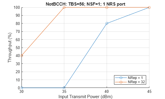
Throughput(%) for 10 transport block(s) at transmit power 30 dBm with 1 repetition(s): 0.0000
Throughput(%) for 10 transport block(s) at transmit power 35 dBm with 1 repetition(s): 0.0000
Throughput(%) for 10 transport block(s) at transmit power 40 dBm with 1 repetition(s): 80.0000
Throughput(%) for 10 transport block(s) at transmit power 45 dBm with 1 repetition(s): 100.0000
Throughput(%) for 10 transport block(s) at transmit power 30 dBm with 32 repetition(s): 40.0000
Throughput(%) for 10 transport block(s) at transmit power 35 dBm with 32 repetition(s): 100.0000
Throughput(%) for 10 transport block(s) at transmit power 40 dBm with 32 repetition(s): 100.0000
Throughput(%) for 10 transport block(s) at transmit power 45 dBm with 32 repetition(s): 100.0000
結果
測定されたスループットを表示します。これは、データ転送に使用可能なリソースを与えられたリンクの最大可能スループットのパーセンテージです。
% Set figure title
if npdschDataType == "SIB1NB"
    npdsch.NSF = 8;
end
figure; grid on; hold on;
legendstr = repmat("",numRep,1);
for repIdx = 1:numRep
    plot(txPower,throughputPercent(:,repIdx),"-o")
    legendstr(repIdx) = "NRep = " + repVal(repIdx);
end
hold off;xlabel('Input Transmit Power (dBm)'); ylabel('Throughput (%)');
title(npdsch.NPDSCHDataType + ": TBS=" + trblklen + ...
    "; NSF=" + npdsch.NSF + "; " + enb_init.NBRefP + " NRS port")
legend(legendstr,Location="southeast")
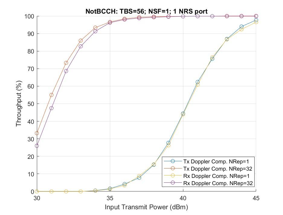
この例の図は、繰り返しインデックス 0 および 5 の 1000 個のトランスポート ブロック (numTrBlks = 1000、txPower = 30:45) をシミュレートすることによって得られたスループット結果を示しています。シミュレーション設定には、デフォルトの上位レイヤー、eNodeB、およびETSI Ricianチャネルを使用した NPDSCH 構成が含まれます。Tx Doppler Comp. に対応する行を取得するには、txDopplerCompensator を true に、rxDopplerCompensator を false に設定します。Rx Doppler Comp. に対応する行については、txDopplerCompensator を false に、rxDopplerCompensator を true に設定できます。
その他の調査
この例では、 NTNチャネルでの NB-IoT NPDSCH のスループット シミュレーションを示します。デフォルトの動作に加えて、これらのケースの例を実行できます。
衛星高度と衛星速度を変化させて、異なる衛星軌道の各送信電力値と繰り返しインデックスでのスループットを解析します。
txDopplerCompensatorおよびrxDopplerCompensator変数をfalseに設定して、ドップラー補正技術を使用せずにリンク パフォーマンスを観察します。txDopplerCompensatorをfalseに、rxDopplerCompensatorをtrueに設定して、受信機のみでドップラー補正のみを使用したリンク パフォーマンスを観察します。iReps値を変更して、さまざまな繰り返しでのスループット パフォーマンスを確認します。NB-IoT NPDSCH Block Error Rate Simulation (LTE Toolbox) の例に示すように、
lteFadingChannel(LTE Toolbox)チャネルを使用して、 NTNと地上ネットワークのスループット パフォーマンスを比較します。
サポート ファイル
この例では、このヘルパー関数を使用します。
hNPDSCHInfo — NB-IoT NPDSCH情報
参考文献
ETSI TS 101 376-5-5 V1.3.1 (2005-02)。GEO- モバイル無線インターフェース仕様(リリース1); パート5:無線インターフェース物理レイヤー仕様; サブパート5:無線送受信; GMR-1 05.005。
ITU-R勧告P.681-11(2019年8月)。「陸上移動衛星業務の設計システムに必要な伝搬データ」P シリーズ; 電波電波伝搬。
3GPP TS 36.211、「物理チャネルと変調」、第 3 世代パートナーシップ プロジェクト、技術仕様グループ無線アクセス ネットワーク、進化型ユニバーサル地上無線アクセス (E-UTRA)。
3GPP TS 36.213、「物理レイヤー手順」、第 3 世代パートナーシップ プロジェクト、技術仕様グループ無線アクセス ネットワーク、進化型ユニバーサル地上無線アクセス (E-UTRA)。
3GPP TS 36.321、「メディア アクセス制御 (MAC) プロトコル仕様」、第 3 世代パートナーシップ プロジェクト、技術仕様グループ無線アクセス ネットワーク、進化型ユニバーサル地上無線アクセス (E-UTRA)。
3GPP TS 36.101、「ユーザー機器 (UE) の無線送信および受信」、第 3 世代パートナーシップ プロジェクト、技術仕様グループ無線アクセス ネットワーク、進化型ユニバーサル地上無線アクセス (E-UTRA)。
3GPP TS 36.104、「基地局(BS)の無線送信および受信」、第 3 世代パートナーシップ プロジェクト、技術仕様グループ無線アクセス ネットワーク、進化型ユニバーサル地上無線アクセス (E-UTRA)。
3GPP TR 36.763、「非地上ネットワーク向けの狭帯域モノのインターネット (NB-IoT) / 拡張マシン型通信 (eMTC) サポートに関する研究 (NTN) (リリース 17)」、第 3 世代パートナーシップ プロジェクト、無線アクセス ネットワーク技術仕様グループ。
3GPP TR 38.803、「new radioアクセス技術に関する研究:「無線周波数 (RF) と共存の側面 (リリース 14)」、第 3 世代パートナーシップ プロジェクト、技術仕様グループ無線アクセス ネットワーク。
3GPP TR 38.811、「非地上ネットワークをサポートするためのnew radio(NR) の研究 (リリース 15)」、第 3 世代パートナーシップ プロジェクト、技術仕様グループ無線アクセス ネットワーク。
O. ハミ、S. カリクナー、B. ヴァシラキス、F.M.ガンヌーシ。「メモリレス後補償技術を使用したパワーアンプのモデル評価とメモリ効果強度の定量化」IEEEマイクロ波理論と技術論文集56巻12号(2008年12月):3170–79。
ローカル関数
この例では、これらのローカル関数を使用します。
function chanOut = setupNTNChannel(channel,sampleRate)
% Setup NTN channel

    % Assign temporary variables for carrier frequency and maximum Doppler
    % shift due to mobile movement
    fc = double(channel.CarrierFrequency);
    c = physconst("LightSpeed");
    maxDoppler = (double(channel.MobileSpeed)*fc)/c;
    elevAngle = double(channel.ElevationAngle);
    h = double(channel.SatelliteAltitude);
    % Calculate the Doppler shift due to satellite movement
    maxDopplerSat = dopplerShiftCircularOrbit(elevAngle,h,channel.MobileAltitude,fc);
    % Check the maximum Doppler shift and sample rate
    if ((maxDoppler+maxDopplerSat) >= (sampleRate/10))
        error("satcom:setupNTNChannel:MaxDoppler", ...
            "The maximum Doppler shift (%d Hz) due to mobile and satellite " + ...
            "movement, must be less than %d Hz which is one-tenth of SampleRate.", ...
            (maxDoppler + maxDopplerSat),sampleRate/10)
    end

    chanOut = struct;
    chanTypeLower = lower(channel.NTNChannelType);
    if chanTypeLower == "etsi rician"
        channelName = "ETSI Rician";
        baseChannel = etsiRicianChannel;
        baseChannel.SampleRate = sampleRate;
        baseChannel.KFactor = channel.KFactor;
        baseChannel.MaximumDopplerShift = maxDoppler;
    elseif chanTypeLower == "itu-r p.681"
        channelName = "ITU-R P.681";
        baseChannel = p681LMSChannel;
        baseChannel.SampleRate = sampleRate;
        baseChannel.Environment = channel.Environment;
        baseChannel.CarrierFrequency = channel.CarrierFrequency;
        baseChannel.MobileSpeed = channel.MobileSpeed;
        baseChannel.ElevationAngle = channel.ElevationAngle;
        baseChannel.AzimuthOrientation = channel.AzimuthOrientation;
        baseChannel.FadingTechnique = "Sum of sinusoids";
        baseChannel.SatelliteDopplerShift = maxDopplerSat;
    end
    baseChannel.RandomStream = "mt19937ar with seed";
    baseChannel.Seed = channel.Seed;

    % Set the channel filter
    chanFilt = comm.ChannelFilter( ...
                SampleRate=sampleRate,PathDelays=0, ...
                NormalizeChannelOutputs=false);

    % Set the output structure
    chanOut.ChannelName = channelName;
    chanOut.CarrierFrequency = fc;
    chanOut.SatelliteAltitude = h;
    chanOut.ElevationAngle = elevAngle;
    chanOut.BaseChannel = baseChannel;
    chanOut.SatelliteDopplerShift = maxDopplerSat;
    chanOut.ChannelFilter = chanFilt;

end

function [out,sampleTimes] = generateNTNChannel(channel,in)
% Generate NTN channel

    if isprop(channel.BaseChannel,'SatelliteDopplerShift')
        [out,~,sampleTimes] = channel.BaseChannel(in);
    else
        % Get the channel information before channel processing
        prevInfo = info(channel.BaseChannel);
        numSamplesStart = prevInfo.NumSamplesProcessed;

        % Get the path gains of base channel
        [~,pathGainsBase] = channel.BaseChannel(in);

        % Get the channel information after channel processing
        postInfo = info(channel.BaseChannel);
        numSamplesEnd = postInfo.NumSamplesProcessed;

        % Get the channel sample times
        sampleTimes = (numSamplesStart:(numSamplesEnd-1)).'/channel.BaseChannel.SampleRate;

        % Apply satellite Doppler shift to the base channel path gains
        pathGains = pathGainsBase.*exp(1i*2*pi*channel.SatelliteDopplerShift*sampleTimes);

        % Perform channel filtering
        out = channel.ChannelFilter(in,pathGains);
    end

end

function out = compensateDopplerShift(enb,inWave,foffset,flag)
% Perform Doppler shift correction

    if flag
        % Correct frequency offset
        out = lteFrequencyCorrect(enb,inWave,foffset);
    else
        out = inWave;
    end

end

function out = estimateDopplerShiftUsingRS(enb,rxWave,refInd, ...
    refSym,flag)
% Estimate the Doppler shift using NPSS

    if flag
        % Set the Windowing field to 0, as this information is not known at
        % the receiver
        enb.Windowing = 0;
        ofdmInfo = lteSCFDMAInfo(enb);
        K = 12;                             % Number of subcarriers
        L = 14;                             % Number of OFDM symbols in slot

        % Initialize temporary variables
        rxWave1 = [rxWave; zeros((mod(size(rxWave,1),2)),1)]; % Append zero, if required
        rxLen = size(rxWave1,1);

        % Generate reference waveform
        refGrid = complex(zeros([K L]));
        refGrid(refInd) = refSym;
        refWave = lteSCFDMAModulate(enb,refGrid);
        refWave = [refWave; zeros((rxLen-size(refWave,1)),1)];

        % Compute the correlation of received waveform with reference
        % waveform
        x_wave = rxWave1.*conj(refWave);

        % Compute FFT of the resultant waveform
        x_fft = fftshift(fft(x_wave));

        % FFT bin values
        fftBinValues = (-rxLen/2:(rxLen/2-1))*(ofdmInfo.SamplingRate/rxLen);

        % Use the FFT bin index corresponding to the maximum FFT value.
        % The FFT bin value corresponding to this bin index is the integer
        % frequency offset.
        [~,binIndex] = max(x_fft);
        out = fftBinValues(binIndex);
    else
        out = 0;
    end

end

function varargout = paMemorylessNonlinearity(paModel,varargin)
% Apply power amplifier nonlinearity (TR 38.803)
% out = paMemorylessNonlinearity(paModel,in,enable) returns the
% impaired output.
% paMemorylessNonlinearity(paModel) returns the plot with the gain and
% phase characteristics of the power amplifier

    if nargin == 1
        in_NoScale = randn(1e6,1,'like',1i);
        scaleFactor = 1/sqrt(2);
        enable = 1;
    else
        in_NoScale = varargin{1};
        scaleFactor = varargin{2};
        enable = varargin{3};
    end

    if enable
        in = scaleFactor*in_NoScale;
        if isa(paModel,"comm.MemorylessNonlinearity")
            % paModel is a comm.MemorylessNonlinearity System object
            out = paModel(in);
            paModelName = "";
        else
            absIn = abs(in);
            paModelName = paModel;
            switch lower(paModel)
                case "2.1ghz gaas"
                    % 2.1GHz GaAs
                    out = (-0.618347-0.785905i) * in + (2.0831-1.69506i) * in .* absIn.^(2) + ...
                        (-14.7229+16.8335i) * in .* absIn.^(2*2) + (61.6423-76.9171i) * in .* absIn.^(2*3) + ...
                        (-145.139+184.765i) * in .* absIn.^(2*4) + (190.61-239.371i)* in .* absIn.^(2*5) + ...
                        (-130.184+158.957i) * in .* absIn.^(2*6) + (36.0047-42.5192i) * in .* absIn.^(2*7);
                otherwise
                    % 2.1GHz GaN
                    out = (0.999952-0.00981788i) * in + (-0.0618171+0.118845i) * in .* absIn.^(2) + ...
                        (-1.69917-0.464933i) * in .* absIn.^(2*2) + (3.27962+0.829737i) * in .* absIn.^(2*3) + ...
                        (-1.80821-0.454331i) * in .* absIn.^(2*4);
            end
        end
    else
        out = in_NoScale;
    end

    if nargout > 0
        varargout{1} = out;
    end

    if nargin == 1 || (nargout == 0)
        % Gain Plot
        inpPower = 20*log10(absIn);
        gain = 20*log10(abs(out))-inpPower;
        figure
        subplot(211)
        plot(inpPower,gain,".")
        grid on
        ylim([-Inf 1])
        xlim([-30 0])
        xlabel("Normalized input power (dB)")
        ylabel("Gain (dB)")
        title("Gain Characteristics of PA Model " + paModelName)

        % Phase Plot
        phase = angle(out.*conj(in))*180/pi;
        subplot(212)
        plot(inpPower,phase,".")
        grid on
        xlim([-30 0])
        xlabel("Normalized input power (dB)")
        ylabel("Phase (deg)")
        title("Phase Characteristics of PA Model " + paModelName)
    end

end

function paChar = getDefaultCustomPA()
% The operating specifications for the LDMOS-based Doherty amplifier are:
% * A frequency of 2110 MHz
% * A peak power of 300 W
% * A small signal gain of 61 dB
% Each row in HAV08_Table specifies Pin (dBm), gain (dB), and phase shift
% (degrees) as derived from figure 4 of Hammi, Oualid, et al. "Power
% amplifiers' model assessment and memory effects intensity quantification
% using memoryless post-compensation technique." IEEE Transactions on
% Microwave Theory and Techniques 56.12 (2008): 3170-3179.

    HAV08_Table = ...
        [-35,60.53,0.01;
        -34,60.53,0.01;
        -33,60.53,0.08;
        -32,60.54,0.08;
        -31,60.55,0.1;
        -30,60.56,0.08;
        -29,60.57,0.14;
        -28,60.59,0.19;
        -27,60.6,0.23;
        -26,60.64,0.21;
        -25,60.69,0.28;
        -24,60.76,0.21;
        -23,60.85,0.12;
        -22,60.97,0.08;
        -21,61.12,-0.13;
        -20,61.31,-0.44;
        -19,61.52,-0.94;
        -18,61.76,-1.59;
        -17,62.01,-2.73;
        -16,62.25,-4.31;
        -15,62.47,-6.85;
        -14,62.56,-9.82;
        -13,62.47,-12.29;
        -12,62.31,-13.82;
        -11,62.2,-15.03;
        -10,62.15,-16.27;
        -9,62,-18.05;
        -8,61.53,-20.21;
        -7,60.93,-23.38;
        -6,60.2,-26.64;
        -5,59.38,-28.75];
    % Convert the second column of the HAV08_Table from gain to Pout for
    % use by the memoryless nonlinearity System object.
    paChar = HAV08_Table;
    paChar(:,2) = paChar(:,1) + paChar(:,2);

end
参考
オブジェクト
関数
トピック
- NB-IoT NPDSCH Block Error Rate Simulation (LTE Toolbox)