このページの内容は最新ではありません。最新版の英語を参照するには、ここをクリックします。
Getting Started with VEX V5 Rotation Sensor
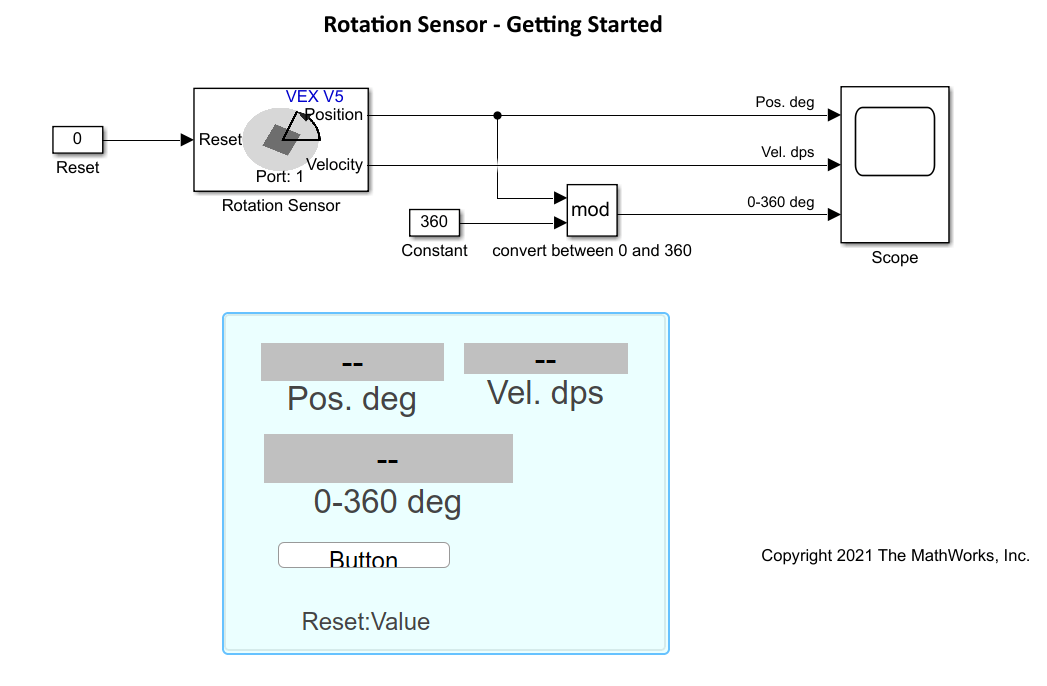
This example shows how to use a VEX® V5 Rotation Sensor with Simulink® Coder™ Support Package for VEX V5 Robot Brain. This example illustrates how to read angular position and velocity of a shaft connected to rotation sensor. Also, it demonstrates how to use a 'Math Function (mod)' for wrapping angle from 0 to 360 degrees.
Prerequisites
If you are new to Simulink, watch the Simulink Quick Start video.
Complete the Getting Started with Simulink Coder Support Package for VEX EDR V5 Robot Brain example.
For instructions to install the Simulink Coder™ Support Package for VEX EDR V5 Robot Brain, see Getting Started with Simulink Coder Support Package for VEX EDR V5 Robot Brain.
Required Hardware
To run this example, you need these hardwares:
VEX EDR V5 Robot Brain
V5 rotation sensor
V5 robot battery
Smart cables and USB A to Micro cable
Connecting the Hardware
1. Connect the V5 robot battery to the VEX EDR V5 Robot Brain.
2. Connect the V5 rotation sensor to port 1 using smart cable.
Model
Open the vexv5_rotationSensor preconfigured Simulink model containing rotation sensor.

Build and Download the Simulink Model
Open the preconfigured model or create a Simulink model, build the model, and download it to the VEX EDR V5 Robot Brain.
1. Connect the V5 Robot Brain to your computer using the USB cable.
2. Open the Simulink model. If you are using the preconfigured model, go to step 5.
3. Open the Modeling tab and press CTRL+E to open Configuration Parameters dialog box.
4. In the Configuration Parameters dialog box, navigate to the Hardware Implementation pane.
Set the Hardware board to VEX V5 Robot Brain.
In the Target Hardware Resources section, set the Build options to Build, load and run to automatically download the binary file on to the connected V5 Robot Brain.
5.Open the Hardware tab and click Build, Deploy & Start. The model is deployed to the V5 Robot Brain. This action builds, downloads, and runs the model as a standalone application on the VEX V5 Robot Brain device.
The user interface displays the shaft position and velocity of the object. Observe the readings on the display. A sample screen is shown below.
