Numerical Consistency of Model and Generated Code Simulation Results
Numerical Consistency
In the Model-Based Design workflow, you use MathWorks® products to generate code for numerical applications that employ fixed-point and floating-point arithmetic.
To develop models, you use MATLAB®, Simulink®, and Stateflow®.
To generate source code, you use Simulink Coder™ and Embedded Coder®.
To test numerical equivalence between your model and generated code, you compare model and generated code simulation results. For example, normal mode simulation results compared with software-in-the-loop (SIL) simulation results.
The results from the model and generated code simulations are numerically consistent if:
In fixed-point applications, the results agree in a bit-wise comparison.
In floating-point applications, the results agree with an error tolerance that you specify.
Use the Simulation Data Inspector to compare results. To determine whether discrepancies exist or are significant, you can specify absolute and relative tolerance values:
For fixed-point applications, you can specify an absolute tolerance of zero.
For floating-point applications, you can specify tolerance with respect to a reference value or signal. The choice of reference depends on your application. Consider these examples:
An algorithm that solves a linear algebraic equation by iterative, feedforward error calculations. You can specify tolerance with respect to
eps.A Proportional-Integral-Derivative (PID) controller for a closed-loop system. For transient behavior, you can specify tolerance with criteria from a standard. For steady-state behavior, you can specify tolerance with reference to the PID controller characteristics.
Programmatically, you can specify absolute and relative
tolerance values through the absTol and relTol properties
of the Simulink.sdi.Signal object.
Numerical Consistency in Complex Systems
For complex systems, numerical differences between model and generated code simulations can be a result of block-level differences propagating through the system. If you observe numerical differences at the system level:
Identify blocks for which block-level numerical differences exceed the error tolerance.
Investigate each identified block.
Consider the following plant-controller model.
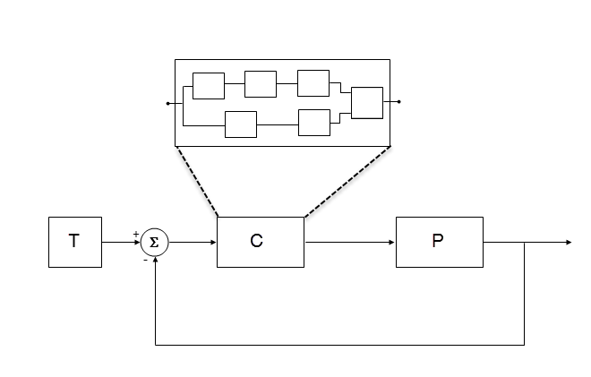
T produces reference or test signals.
C is the controller component. The controller output is the plant input. C can be a Model block that comprises multiple Model blocks.
P is the plant component. The plant output is subtracted from the reference signal to produce the controller input.
To test numerical equivalence between the model controller and the generated code version:
Run the model in normal mode, and, using the Simulation Data Inspector, record the output of C.
Specify SIL mode for C. Rerun the simulation, recording the output of C.
Using the Simulation Data Inspector, compare normal and SIL mode outputs with reference to your specified error tolerance.
If the Simulation Data Inspector comparison indicates a match, the model and generated code results are numerically consistent.
If the normal and SIL mode outputs do not match:
Within C, enable signal logging for block outputs.
Run the model in normal mode.
Rerun the simulation with C in SIL mode.
Using the Simulation Data Inspector, compare the logged output signals with reference to your specified error tolerance. See Compare Simulation Data.
Identify blocks for which normal and SIL mode output differences exceed the error tolerance.
Analyze each identified block and look for the cause. For example, the generated code might use a different math library than MATLAB.
Note
If the comparison of a large number of signals is required, you can automate the workflow with Simulink Test™. See SIL Verification for a Subsystem (Simulink Test).
Reasons for Block-Level Numerical Differences
In fixed-point and floating-point application development, there are factors that can affect numerical agreement between block-level results from model and generated code simulations.
Some factors can affect both fixed-point and floating-point applications. For example, the use of:
Code generation optimization.
Custom code.
Code replacement library entries whose results differ from MATLAB results.
Code replacement libraries that implement different algorithms.
Other factors affect only floating-point applications. For example:
Numerical soundness of algorithm.
Algorithm sensitivity to input.
Closed loop and open loop behavior.
References
[1] IEEE® Standard on Transitions, Pulses, and Related Waveforms, IEEE Standard 181, 2003, pp. 15–17.
See Also
Topics
- Analyze Simulation Results
- SIL Verification for a Subsystem (Simulink Test)
- Differences Between Generated Code and MATLAB Code
- Types of In-the-Loop Testing in the V-Model (Embedded Coder)
- MATLAB Function
- SIL and PIL Limitations (Embedded Coder)