Wireless Control Between BBC micro:bit Boards
This example shows you how to use Simulink® models for wireless communication and control between two BBC micro:bit boards.
Introduction
The Simulink® Coder Support Package for BBC micro:bit provides Radio blocks that help you to use wireless radio communication over a dedicated channel between two or more BBC micro:bit boards.
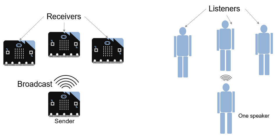
To view the Radio blocks, open the Simulink Library Browser and navigate to BBC Micro:bit Radio block library. The library contains a Radio Receive block and a Radio Transmit block. The Radio Transmit block sends data from a BBC micro:bit. If one BBC micro:bit is sending data, multiple BBC micro:bit boards in its vicinity can receive the data. In this case, the sender is like one person speaking, each receiver is like one of many people listening.
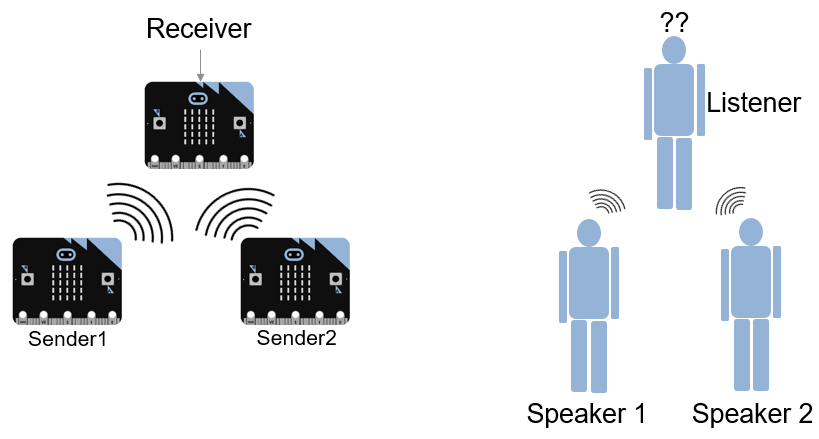
If more than one board is sending data at the same time in the same channel, the sent data is corrupted and the receiver receives improper data. In this case, the senders are like two people talking at the same time. The receiver is like a listener trying to follow more than one speaker at the same time.
The problem with corrupted data from multiple senders can be avoided by using different channels.
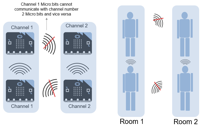
The Radio blocks in BBC micro:bit can operate at different channels, numbered from 1 to 100. Each channel works at a different frequency. If a few BBC micro:bit boards are sending and receiving data using one channel, the BBC micro:bit boards operating at other channels cannot receive the data even if they are physically close to the sending (or transmitting) BBC micro:bit.
A channel can be visualized as a closed room. The speaker and listeners are in the closed room. The speaker in one room cannot be heard from the other rooms. In one room, multiple listeners can be present. Listeners in a room can hear the speaker in that room.
In this example, you learn about two Simulink models that are designed for wireless communication and control using the Radio blocks:
The Radio Transmit model, when deployed on the first BBC micro:bit (Tx), tracks the tilt of the board along the x-axis using the accelerometer sensor. The board then transmits this data over a radio channel.
The Radio Receive model, when deployed on the second BBC micro:bit (Rx), receives the data from the transmitting BBC micro:bit. The receiving board then displays a left or right arrow on the LED matrix to indicate the tilt direction of the Tx BBC micro:bit.
Prerequisites
If you are new to Simulink, complete the Interactive Simulink Tutorial.
If you are new to Simulink Coder, visit the Simulink Coder product page for an overview and tutorials.
Complete Getting Started with Simulink Coder Support Package for BBC micro:bit.
Required Hardware
To run this example you need this hardware:
Two BBC micro:bit boards
Battery pack (the one provided with the BBC micro:bit board)
USB type A to Micro-B cable
Task 1 - Deploy the Two Models and Observe the Display
1. Connect the Tx BBC micro:bit to your development computer. For details about the USB connection between BBC micro:bit and development computer, see Getting Started with Simulink Coder Support Package for BBC micro:bit.
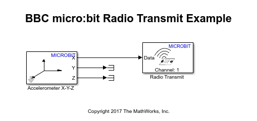
2. Open the example model bbcmicrobit_radio_transmit.
3. In Simulink model window, on the Hardware tab, click Build, Deploy & Start.
4. After the code deployment is successful, unplug this Tx BBC micro:bit from USB, and connect the battery pack to it. This board continues to function as the transmitter.
5. Connect the Rx BBC micro:bit to your development computer.
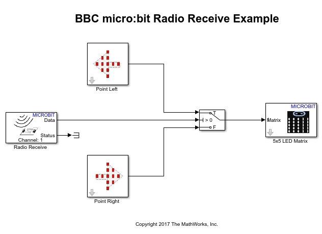
6. Open the example model bbcmicrobit_radio_receive.
7. In Simulink model window, on the Hardware tab, click Build, Deploy & Start.
8. Tilt the Tx BBC micro:bit along the x-axis.
You can observe that the arrow on the Rx BBC micro:bit changes direction based on the direction of the tilt of the Tx BBC micro:bit.
Task 2 - Understand How the Simulink Models Work
Radio Transmit Model
In the bbcmicrobit_radio_transmit model, the tilt of the BBC micro:bit is obtained by reading the Accelerometer block X output. The X output is directly connected to the Radio Transmit block and the channel number is set to a particular value. The Radio Transmit block transmits the accelerometer data to a BBC micro:bit that is receiving data on the same channel.
Radio Receive Model:
In the bbcmicrobit_radio_receive model, the Radio Receive block receives the data from the transmitting BBC micro:bit. Ensure that the Radio Receive block is configured for the same channel as the Radio Transmit block. Additionally, the Radio Receive block is also configured with Data length set to 1 (for interpreting data of one axis only) and the Data type as double. The 5x5 LED Matrix block is used to display the arrow (Point Left block and Point Right block) based on the output from a Switch block.
If you are using the BBC micro:bit V2 board, you must enable the Interrupt for LED Matrix using these steps.
1. In your Simulink model, click Modeling > Model Settings to open the Configuration Parameters dialog box.
2. In the Configuration Parameters dialog box, select the Hardware Implementation pane, click Target hardware resources > LED Matrix and select Enable for Interrupt option. Click Apply and OK.
Other Things to Try with Radio Blocks
Implement the same logic for
y-axi. Tip: Use |_Y_-axisdata from accelerometer sensor on Tx BBC micro:bit and use the Point Up and Point Down blocks in Rx BBC micro:bit.
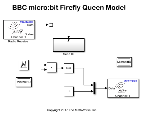
Create a system with few BBC micro:bits, in which only one BBC micro:bit switches ON at once, based on radio communication.
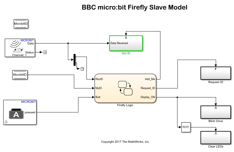
Tip: Use the bbcmicrobit_fireFly_queen model on one BBC micro:bit, which assigns unique IDs to multiple BBC micro:bits, and later broadcasts a random ID.
Use the bbcmicrobit_fireFly_Slave model on each of the remaining BBC micro:bits, which flashes an LED when it receives an ID or responds to the broadcast from the Queen BBC micro:bit.