traceTee
Description
Use the traceTee object to create a tee trace on the X-Y
plane.
Note
This shape object supports behavioral modeling. For more information, see Behavioral Models.
Creation
Description
trace = traceTee creates a tee trace with default properties on
the X-Y plane.
trace = traceTee( sets Properties using one or more
name-value arguments. For example, Name=Value)traceTee(ReferencePoint=[1 1])
creates a tee trace with the reference point [1 1]. Properties not
specified retain their default values.
Properties
Object Functions
add | Boolean unite operation on two RF PCB shapes |
subtract | Boolean subtraction operation on two RF PCB shapes |
intersect | Boolean intersection operation on two RF PCB shapes |
plus | Shape1 + Shape2 for RF PCB shapes |
minus | Shape1 - Shape2 for RF PCB shapes |
mirrorX | Mirror shape along X-axis |
mirrorY | Mirror shape along Y-axis |
and | Shape1 & Shape2 for RF PCB shapes |
area | Calculate area of RF PCB shape in square meters |
rotate | Rotate RF PCB shape about defined axis |
rotateX | Rotate RF PCB shape about x-axis |
rotateY | Rotate RF PCB shape about y-axis and angle |
rotateZ | Rotate RF PCB shape about z-axis |
translate | Move RF PCB shape to new location |
scale | Change size of RF PCB shape by fixed amount |
Examples
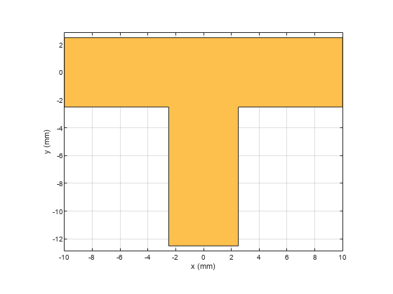
Create a tee trace with default properties.
trace = traceTee
trace =
  traceTee with properties:

              Name: 'mytraceTeeShape'
    ReferencePoint: [0 0]
            Length: [0.0200 0.0100]
             Width: [0.0050 0.0050]
            Offset: 0
View the trace.
show(trace)
Design a microstrip transmission line at 3 GHz for FR4 substrate.
m = design(microstripLine('Substrate',dielectric('FR4')),3e9);
Create a microstrip T-junction.
layer2d = traceTee('Length',[m.Length m.Length/4],...
"Width",[m.Width m.Width/2]);
Convert the T-junction trace to a 3-D component.
robj = pcbComponent(layer2d);
robj.BoardThickness = m.Substrate.Thickness;
robj.Layers{2} = m.Substrate;
show(robj)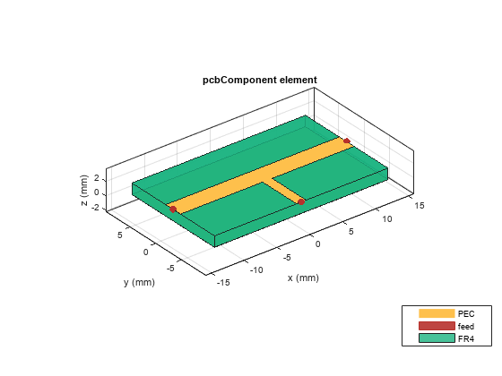
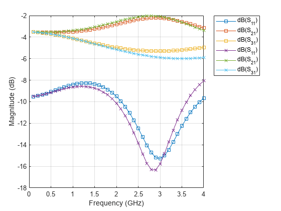
Define frequency points to calculate the s-parameters.
freq = (1:40)*100e6;
Calculate the s-parameters of the T-junction trace using the behavioral model.
Sckt = sparameters(robj,freq,75,'Behavioral',true);Warning: Behavioral model is valid only when Z0 of main line is 50 ohms and for EpsilonR of 9.9.
Calculate the s-parameters of the T-junction trace using the electromagnetic solver.
Sem = sparameters(robj,freq,75)
Sem =
  sparameters: S-parameters object

       NumPorts: 3
    Frequencies: [40×1 double]
     Parameters: [3×3×40 double]
      Impedance: 75

  rfparam(obj,i,j) returns S-parameter Sij
Plot the s-parameter data using the rfplot function.
rfplot(Sckt,1:3,1,'db','-s')
hold on
rfplot(Sem,1:3,1,'db','-x')
References:
Ramesh Garg & I. J. Bahl (1978) Microstrip discontinuities, International Journal of Electronics, 45:1, 81-87, DOI: 10.1080/00207217808900883
Wadell, Brian C. Transmission Line Design Handbook. The Artech House Microwave Library. Boston: Artech House, 1991.
Version History
Introduced in R2021b
See Also
traceLine | traceCross | traceRectangular | tracePoint | traceSpiral