Main Content

minvarweights

Weights for minimum-variance array pattern synthesis

Since R2022b

    Description

    wts = minvarweights(pos,ang) computes the minimum-variance weights wts for synthesizing the pattern of a sensor array in the directions specified by ang. Array element positions are specified in pos. The function optimizes the beamforming weights using a second-order cone programming solver. This function requires Optimization Toolbox™.

    example

    wts = minvarweights(pos,ang,cov) also specifies the spatial covariance matrix cov of the array elements.

    example

    wts = minvarweights(___,MaskAngle=angm) also specifies angles angm at which mask sidelobe levels are defined in the sllm argument.

    example

    wts = minvarweights(___,MaskSidelobeLevel=sllm) also specifies maximum allowable sidelobe levels sllm at the angles defined in angm.

    example

    wts = minvarweights(___,NullAngle=angn) also specifies null directions angn for the array.

    example

    Examples

    collapse all

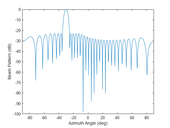
    Compute optimized beamforming weights of a 31-element half-wavelength spacing ULA in the direction of -30 degree in azimuth. Design the array to keep sidelobe levels less than -23 dB.

    Create the optimized weights.

    N = 31;
    pos = (0:N-1)*0.5;
    sll = -23;
    wts = minvarweights(pos,-30,MaskSidelobeLevel=sll);

    Apply the optimized weights and display the array pattern from -90 to +90 azimuth.

    az = -90:.25:90;
    pat_opt = arrayfactor(pos,az,wts);
    plot(az,mag2db(abs(pat_opt)))
    xlabel('Azimuth Angle (deg)')
    ylabel('Beam Pattern (dB)')
    xlim([-90,90])

    Figure contains an axes object. The axes object with xlabel Azimuth Angle (deg), ylabel Beam Pattern (dB) contains an object of type line.

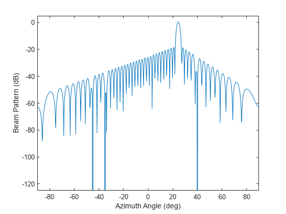
    Design an array to have a tapered beampattern, The array is a 51-element half-wavelength spacing ULA steered in the direction of 25 in azimuth. The pattern synthesis goal is to achieve sidelobe levels smaller than a tapered mask decreasing linearly from -18 dB to -55 dB at ±90. Place nulls at -35, -45, and 40 azimuth angle.

    N = 51;
    pos = (0:N-1)*0.5;
    ANGmainBeam = 25;
    angn = [-35 -45 40];
    angm = [-90:.2:22 27:0.2:90];
    sllm = [linspace(-55,-18,length(-90:.2:22)) ...
        linspace(-18,-55,length(27:.2:90))];
    wts = minvarweights(pos,ANGmainBeam,'MaskAngle',angm, ...
        'MaskSidelobeLevel',sllm,'NullAngle',angn);

    Apply optimized weights and display the array pattern from -90 to +90 in azimuth.

    az = -90:.25:90;
    pat_opt = arrayfactor(pos,az,wts);
    plot(az,mag2db(abs(pat_opt)))
    axis([-90 90 -125 5])
    xlabel('Azimuth Angle (deg)')
    ylabel('Beam Pattern (dB)')

    Figure contains an axes object. The axes object with xlabel Azimuth Angle (deg), ylabel Beam Pattern (dB) contains an object of type line.

    Verify that nulls are placed at -35, -45, and 40 azimuth angle.

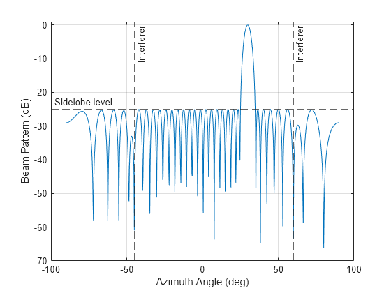
    Calculate the optimized beamforming weights for a 32-element, half-wavelength spacing ULA. The look direction (angs) is 30 degrees in azimuth. There are two interfering signals coming from azimuths 60 and -45 degrees, respectively (angi). The signal-free spatial covariance matrix contains contributions from the noise and the interferers only. The noise is white across all elements and the SNR (snr) is 10 dB. The pattern synthesis goal is to keep the sidelobe level (sll) below -25 dB and to point nulls at the interferers.

    N = 32;
    d = 0.5;
    pos = (0:N-1)*d;
    angs = 30;
    angi = [-45 60];

    Find the sensor covariance matrix and then the array weights.

    snr= 10;
    cov = sensorcov(pos,angi,db2pow(-snr));
    sll = -25;
    wts = minvarweights(pos,angs,cov,'MaskSidelobeLevel',sll);

    Find the array pattern.

    az = -90:.25:90;
    pat_opt = arrayfactor(pos,az,wts);

    Plot the array pattern as a function of azimuth (az).

    plot(az,mag2db(abs(pat_opt)))
    xline(angi(1),'--','Interferer')
    xline(angi(2),'--','Interferer')
    yline(sll,'--','Sidelobe level', ...
        'LabelHorizontalAlignment','left')
    xlabel('Azimuth Angle (deg)')
    ylabel('Beam Pattern (dB)')
    ylim([-70 1])
    grid on

    Figure contains an axes object. The axes object with xlabel Azimuth Angle (deg), ylabel Beam Pattern (dB) contains 4 objects of type line, constantline.

    Input Arguments

    collapse all

    Positions of the elements of a sensor array, specified as a 1-by-N vector, a 2-by-N matrix, or a 3-by-N matrix. In this vector or matrix, N represents the number of elements of the array. Each column of pos represents the coordinates of an element. If pos is a 1-by-N vector, then it represents the y-coordinate of the sensor elements of a line array. The x and z-coordinates are assumed to be zero. When pos is a 2-by-N matrix, it represents the (y,z)-coordinates of the sensor elements of a planar array. This array is assumed to lie in the yz-plane. The x-coordinates are assumed to be zero. When pos is a 3-by-N matrix, then the array can have an arbitrary shape. Sensor positions are in terms of signal wavelength.

    Example: [0,0,0; 0.1,0.4,0.3; 1,1,1]

    Data Types: double

    Beamforming directions, specified as a 1-by-M vector or a 2-by-M matrix. In this vector or matrix, M represents the number of incoming signals. If ang is a 2-by-M matrix, each column specifies the direction in azimuth and elevation of the beamforming direction as [az;el]. Angular units are specified in degrees. The azimuth angle must lie between –180° and 180° and the elevation angle must lie between –90° and 90°. The azimuth angle is the angle between the x-axis and the projection of the beamforming direction vector onto the xy plane. The angle is positive when measured from the x-axis toward the y-axis. The elevation angle is the angle between the beamforming direction vector and xy-plane. It is positive when measured towards the positive z axis. If ang is a 1-by-M vector, then it represents a set of azimuth angles with the elevation angles assumed to be zero.

    Example: [45;10]

    Data Types: double

    Sensor spatial covariance matrix, specified as an N-by-N complex-valued positive-definite matrix. N is the number of array sensor elements. cov is a signal-free covariance matrix, which means it does not contain the signals of interest and includes only contributions from spatial noise and interference. The default value is the identity matrix indicating isotropic spatially white noise with unit variance. You can use the sensorcov function to generate a sensor covariance matrix.

    Example: [5,0.1;0.1,2]

    Data Types: double
    Complex Number Support: Yes

    Angles at which mask sidelobe levels are defined, specified as a real-valued 1-by-K vector or a real-valued 2-by-K matrix where K is the number of mask sidelobe levels. If angm is a 1-by-K vector, then it contains the azimuth angles of the mask directions. If angm is a 2-by-K matrix, each column specifies the direction in the form [az;el] where az stands for azimuth and el stands for elevation. Angle units are in degrees.

    Data Types: double

    Maximum allowable mask sidelobe levels, specified as a non-positive scalar or non-positive real-valued 1-by-K vector. K is the number of mask sidelobe levels. Sidelobe levels are always less than or equal to zero.

    • If sllm is a scalar, then it contains a uniform mask for all sidelobe levels and angm must be empty.

    • If sllm is a 1-by-K vector, then sllm and angm must have the same number of columns; and sllm contains the mask sidelobe levels for corresponding mask angles, angm.

    An empty sllm vector means that there are no constraints on the sidelobe levels. Units are in dB.

    Data Types: double

    Null direction angles, specified as either a 1-by-P vector or a 2-by-P matrix where P is the number of null directions. If angn is a 1-by-P vector, then it contains only the azimuth angles of directions. If angn is a 2-by-P matrix, each column specifies the null direction in the form [az;el] where az stands for azimuth and el stands for elevation. Angle units are in degrees.

    Data Types: double

    Output Arguments

    collapse all

    Beamformer weights, returned as a complex-valued N-by-1 vector. N represents the number of sensor elements of the array. The optimization procedure determining wts attempts to find array weights wts such that the resulting pattern has nulls in the directions of any interferers present in cov.

    References

    [1] Lebret, H., and S. Boyd. “Antenna Array Pattern Synthesis via Convex Optimization.” IEEE Transactions on Signal Processing, vol. 45, no. 3, Mar. 1997, pp. 526–32. DOI.org (Crossref), https://doi.org/10.1109/78.558465.

    [2] Golbon-Haghighi, Mohammad-Hossein, et al. “Design of a Cylindrical Crossed Dipole Phased Array Antenna for Weather Surveillance Radars.” IEEE Open Journal of Antennas and Propagation, vol. 2, 2021, pp. 402–11. DOI.org (Crossref), https://doi.org/10.1109/OJAP.2021.3059471.

    Version History

    Introduced in R2022b