Vector Field Histogram
The vector field histogram (VFH) algorithm computes obstacle-free steering directions for a robot based on range sensor readings. Range sensor readings are used to compute polar density histograms to identify obstacle location and proximity. Based on the specified parameters and thresholds, these histograms are converted to binary histograms to indicate valid steering directions for the robot. The VFH algorithm factors in robot size and turning radius to output a steering direction for the robot to avoid obstacles and follow a target direction.
Robot Dimensions
To calculate steering directions, you must specify information about the robot size and its
driving capabilities. The VFH algorithm requires only four input parameters for the
robot. These parameters are properties of the controllerVFH object: RobotRadius,
SafetyDistance, MinTurningRadius, and
DistanceLimits.
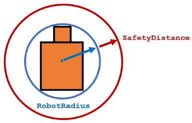
RobotRadiusspecifies the radius of the smallest circle that can encircle all parts of the robot. This radius ensures that the robot avoids obstacles based on its size.
SafetyDistanceoptionally specifies an added distance on top of theRobotRadius. You can use this property to add a factor of safety when navigating an environment.
MinTurningRadiusspecifies the minimum turning radius for the robot traveling at the desired velocity. The robot may not be able to make sharp turns at high velocities. This property factors in navigating around obstacles and gives it enough space to maneuver.
DistanceLimitsspecifies the distance range that you want to consider for obstacle avoidance. You specify the limits in a two-element vector,[lower upper]. Thelowerlimit is used to ignore sensor readings that intersect with parts on the robot, sensor inaccuracies at short distances, or sensor noise. Theupperlimit is the effective range of the sensor or is based on your application. You might not want to consider all obstacles in the full sensor range.
Note
All information about the range sensor readings assumes that your range finder is mounted in the center of your robot. If the range sensor is mounted elsewhere, transform your range sensor readings from the laser coordinate frame to the robot base frame.
Cost Function Weights
Cost function weights are used to calculate the final steering
directions. The VFH algorithm considers multiple steering directions
based on your current, previous, and target directions. By setting
the CurrentDirectionWeight, PreviousDirectionWeight,
and TargetDirectionWeight properties, you can
modify the steering behavior of your robot. Changing these weights
affects the responsiveness of the robot and how it reacts to obstacles.
To make the robot head towards its goal location, set TargetDirectionWeight higher
than the sum of the other weights. This high TargetDirectionWeight value
helps to ensure the computed steering direction is close to the target
direction. Depending on your application, you might need to tune these
weights.
Histogram Properties
The VFH algorithm calculates a histogram based on the given range sensor data. It takes all
directions around the robot and converts them to angular sectors that are specified by
the NumAngularSectors property. This property is non-tunable and
remains fixed once the controllerVFH object is called. The range
sensor data is used to calculate a polar density histogram over these angular sectors.

Note
Using a small NumAngularSectors value can
cause the VFH algorithm to miss smaller obstacles. Missed obstacles
do not appear on the histogram.
This histogram displays the angular sectors in blue and the
histogram thresholds in pink. The HistogramThresholds property
is a two-element vector that determines the values of the masked histogram,
specified as [lower upper]. Polar obstacle density
values higher than the upper threshold are represented as occupied
space (1) in the masked histogram. Values smaller than the lower threshold
are represented as free space (0). Values that fall between the limits
are set to the values in the previous binary histogram, with the default
being free space (0). The masked histogram also factors in the MinTurningRadius, RobotSize,
and SafetyDistance.
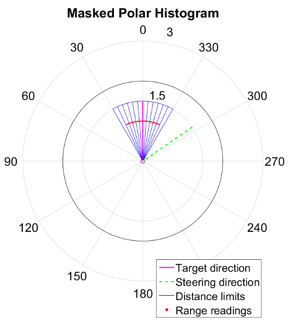
The polar density plot has the following corresponding masked histogram plot. This plot shows the target and steering directions, range readings, and distance limits.

Tune Parameters Using show
When working with a controllerVFH object, you can visualize the
properties and parameters of the algorithm using the show function.
This method displays the polar density plot and masked binary histogram. It also
displays the algorithm parameters and the output steering direction for the VFH.

You can then tune parameters to help you prototype your obstacle avoidance application. For example, if you see that certain obstacles do not appear in the Masked Polar Histogram plot (right), then in the Polar Obstacle Density plot, consider adjusting the histogram thresholds to appropriate values. After you make the adjustments in the Masked Polar Histogram plot, the range sensor readings, shown in red, should match up with locations in the masked histogram (blue). Also, you can see the target and steering directions. You specify the target direction. The steering direction is the main output from the VFH algorithm. Adjusting the Cost Function Weights can help you tune the output of the final steering direction.
Although you can use the show method in a
loop, it slows computation speed due to the graphical plotting. If
you are running this algorithm for real-time applications, get and
display the VFH data in separate operations.