Inverse Clarke Transform
Implement αβ to abc transformation
Libraries:
Motor Control Blockset /
Controls /
Math Transforms
Motor Control Blockset HDL Support /
Controls /
Math Transforms
Description
The Inverse Clarke Transform block computes the Inverse Clarke
transformation of balanced, two-phase orthogonal components in the stationary
αβ reference frame and outputs the balanced, three-phase components in
the stationary abc reference frame. Alternatively, the block can compute
Inverse Clarke transformation of the components α, β,
and 0 to output the three-phase components a,
b, and c. For a balanced system, the zero component is
equal to zero. Use the Number of inputs parameter to use either two or
three inputs.
The block accepts the α-β axis components as inputs and outputs the corresponding three-phase signals, where the phase-a axis aligns with the α-axis.
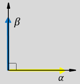
The α and β input components in the αβ reference frame.
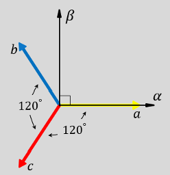
The direction of the equivalent a, b, and c output components in the abc reference frame and the αβ reference frame.
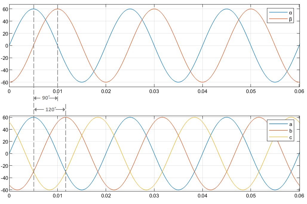
The time-response of the individual components of equivalent balanced αβ and abc systems.
Equations
The following equation describes the Inverse Clarke transform computation:
For balanced systems like motors, the zero sequence component calculation is always zero:
Therefore, you can use only two current sensors in three-phase motor drives, where you can calculate the third phase as,
By using these equations, the block implements the Inverse Clarke transform as,
where:
and are the balanced two-phase orthogonal components in the stationary αβ reference frame.
is the zero component in the stationary αβ reference frame.
, , and are the balanced three-phase components in the abc reference frame.
Ports
Input
Output
Parameters
Extended Capabilities
Version History
Introduced in R2020a