Uplink Control Channel Format 1
The physical uplink control channel format 1 is a transmission channel used to carry information regarding scheduling requests in which the UE requests resources to transmit UL-SCH. It is also used to send acknowledgment responses and retransmission requests (ACK and NACK).
Uplink Control Information on PUCCH Format 1
Format 1 uplink control information (UCI) contains scheduling requests and acknowledgment responses or retransmission requests (ACK and NACK).
Channel Coding for UCI HARQ-ACK
The HARQ acknowledgment bits are received from higher layers. Depending on the number of codewords present, a HARQ acknowledgment consists of 1 or 2 information bits. A positive acknowledgment (ACK) is encoded as a binary 1, while a negative acknowledgment (NACK) is encoded as a binary 0. The HARQ-ACK bits are then processed, as required by the PUCCH.
Channel coding for UCI Scheduling Request
The scheduling request indication is received from higher layers. Zero information bits are used to request resources to transmit UL-SCH. However, the eNodeB knows when to expect a scheduling request from each UE within the cell. Therefore, if PUCCH energy is detected, the eNodeB will identify it as a scheduling request from the corresponding UE.
PUCCH Format 1, 1a, and 1b
The various PUCCH Format 1 messages used are identified by the type of control information they carry and the number of control bits they require per subframe. The three PUCCH format 1 types, their modulation schemes, and the number of information bits they use are shown in the following table.
| PUCCH format | Modulation scheme | Number of bits per subframe, Mbit | Type of control information |
|---|---|---|---|
| 1 | n/a | n/a | Scheduling request |
| 1a | BPSK | 1 | HARQ-ACK (1 bit) |
| 1b | QPSK | 2 | HARQ-ACK (2 bits) |
The bandwidth available during one subframe of a single resource block exceeds that needed for the control signaling information of a single user terminal. To make efficient use of the available resources, the resource block can be shared by multiple user terminals. Even though the same RB is used for the PUCCH Formats 1, 1a and 1b, there is no possibility of intra-cell interference if different cyclic shifts of the same base reference sequence are used. Moreover, for PUCCH Formats 1, 1a and 1b, an extra degree of freedom is provided by applying an orthogonal cover code.
Format 1
A request for uplink resources can be made by means of the random access channel. However, due to the probability of collisions during high intensity periods, an alternative method is provided using the PUCCH Format 1.
Each UE in the cell is assigned a specific resource index mapping, a resource which can be used every nth frame to transmit a scheduling request. Therefore, if PUCCH energy is detected, the eNodeB will identify it as a scheduling request from the corresponding UE. Since each UE will have a specific resource allocated, there is no probability of a collision. However, the number of available PUCCH resources is reduced.
Format 1a and 1b
For transmission of the hybrid-ARQ acknowledgment, the HARQ ACK bits are used to generate a BPSK/QPSK symbol, depending on the number of codewords present. The modulated symbol is then used to generate the signal to be transmitted in each of the two PUCCH slots.
Demodulation Reference Signals on PUCCH Format 1
Demodulation reference signals associated with the PUCCH format 1 are used by the base station to perform channel estimation and allow for coherent demodulation of the received signal.
These reference signals are time-multiplexed with data, whereas in the downlink there is both time and frequency multiplexing. This multiplexing is performed to maintain the single-carrier nature of the SC-FDMA signal, which ensures that all data carriers are contiguous.
DRS Generation
The demodulation reference signals are generated using a base sequence denoted by , which is discussed further in Base Sequence. More specifically, is used to denote the PUCCH format 1 DRS sequence and is defined by the following equation.
It is desired that the DRS sequences have small power variations in time and frequency, resulting in high power amplifier efficiency and comparable channel estimation quality for all frequency components. Zadoff-Chu sequences are good candidates, since they exhibit constant power in time and frequency. However, there are a limited number of Zadoff-Chu sequences; therefore, they are not suitable on their own.
The generation and mapping of the DRS associated with the PUCCH format 1 are discussed further in the following sections.
Base Sequence. The demodulation reference signals are defined by a cyclic shift, α, of a base sequence, r.
The base sequence, r, is represented in the following equation.
The preceding equation contains the following variables.
, where is the length of the reference signal sequence.
is the base sequence group number.
is the sequence number within the group and only applies to reference signals of length greater than 6 resource blocks.
A phase rotation in the frequency domain (pre-IFFT in the OFDM modulation) is equivalent to a cyclic shift in the time domain (post IFFT in the OFDM modulation). For frequency non-selective channels over the 12 subcarriers of a resource block, it is possible to achieve orthogonality between DRS generated from the same base sequence if for , and assuming the DRS are synchronized in time.
The orthogonality can be exploited to transmit DRS at the same time, using the same frequency resources without mutual interference. In the PUCCH format 1 case, an extra degree of freedom can be achieved by applying an orthogonal cover code, . Generally, DRS generated from different base sequences will not be orthogonal; however, they will present low cross-correlation properties.
To maximize the number of available Zadoff-Chu sequences, a prime length sequence is needed. The minimum sequence length in the UL is 12, the number of subcarriers in a resource block, which is not prime.
Therefore, Zadoff-Chu sequences are not suitable by themselves. There are effectively the following two types of base reference sequences.
those with a sequence length ≥ 36 (spanning 3 or more resource blocks), which use a cyclic extension of Zadoff-Chu sequences
those with a sequence length ≤ 36 (spanning 2 resource blocks), which use a special QPSK sequence
![]() Base sequences of length ≥ three resource blocks
Base sequences of length ≥ three resource blocks
![]() Base sequences of length ≤ three resource blocks
Base sequences of length ≤ three resource blocks
DRS Grouping. There are a total of 30 sequence groups, , each containing one sequence for length less than or equal to 60. This corresponds to transmission bandwidths of 1,2,3,4 and 5 resource blocks. Additionally, there are two sequences (one for v = 0 or 1) for length ≥ 72; corresponding to transmission bandwidths of 6 resource blocks or more.
Note that not all values of m are allowed, where m is the number of resource blocks used for transmission. Only values for m that are the product of powers of 2, 3 and 5 are valid, as shown in the following equation.
The reason for this restriction is that the DFT sizes of the SC-FDMA precoding operation are limited to values which are the product of powers of 2, 3 and 5. The DFT operation can span more than one resource block, and since each resource block has 12 subcarriers, the total number of subcarriers fed to the DFT will be 12m. Since the result of 12m has to be the product of powers of 2, 3 and 5 this implies that the number of resource blocks must themselves be the product of powers of 2, 3 and 5. Therefore values of m such as 7, 11, 14, 19, etc. are not valid.
For a given time slot, the uplink reference signal sequences to use within a cell are taken from one specific sequence group. If the same group is to be used for all slots then this is known as fixed assignment. On the other hand, if the group number u varies for all slots within a cell this is known as group hopping.
PUCCH Format 1 Resource Element Mapping
The resource blocks assigned to L1/L2 control information within a subframe are located at the edges of the total available cell bandwidth. A frequency hopping pattern is used where the lower end of the available UL spectrum is used in the first slot of the subframe and the higher end on the second; this adds a level of frequency diversity.
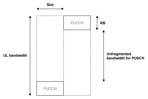
Bandwidth edges are used so that a large unfragmented portion of the spectrum remains to allocate to the PUSCH. If this spectrum was fragmented by multiple PUCCHs it would not be possible to allocate a number of contiguous RBs to a UE, hence the single carrier nature of SC-FDMA would be lost.
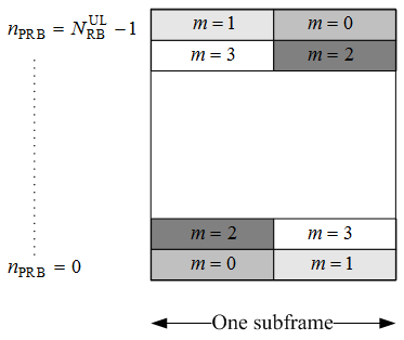
There is a single index, m, derived from the PUCCH resource index and other parameters that specifies the location of the PUCCH in time/frequency. When m is 0, the PUCCH occupies the lowest RB in the first slot and the highest RB in the second slot of a subframe. When m is 1, the opposite corners are used—the highest RB in the first slot and the lowest RB in the second slot. As m increases further, the allocated resource blocks move in towards the band center as shown in the following figure.
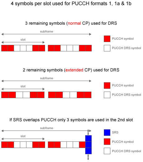
PUCCH formats 1, 1a, and 1b make use of four SC-FDMA symbols per slot. If normal cyclic prefix is used, the remaining 3 symbols, 2 for extended cyclic prefix, are used for PUCCH demodulation reference signal (DRS). If the sounding reference signal (SRS) overlaps the PUCCH symbols, only three symbols are used in the second slot of the subframe. The mapping of the symbols is illustrated in the following figure.
See Also
ltePUCCH1 | ltePUCCH1Indices | ltePUCCH1DRS | ltePUCCH1DRSIndices | lteULResourceGrid