2 タンク システム: 連続時間 SISO システムの C MEX ファイル モデリング
この例では、C MEX モデル ファイルに基づいて IDNLGREY モデリングを実行する方法を説明します。この例では単純なシステムを使用するため、非線形の状態空間モデリングが適しています。
2 タンク システム
ここでの目的は、実験室規模の 2 タンク システムの下部タンクの水位をモデリングすることです。図 1 に概要を示します。
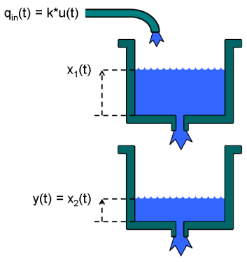
図 1: 2 タンク システムの概略図
入出力データ
モデル化のジョブを、使用できる入出力データの読み込みから始めます。このデータは、以下の IDNLGREY モデル構造を使用してシミュレートし、出力にノイズを追加したものです。twotankdata.mat ファイルには、サンプリング レート (Ts) 0.2 秒を使用して生成された 3000 個の入出力サンプルがあるデータセットが 1 つあります。入力 u(t) はポンプに印加された電圧 [V] で、上部タンクへの流入を生成します。この上部タンクの底部にある小さな穴から流出し、下部タンクに流れ込みます。2 タンク システムの出力 y(t) は下部タンクの水位 [m] です。タンク データを格納する IDDATA オブジェクト z を作成します。記録とドキュメンテーションのため、チャネル名と単位も指定します。このステップはオプションです。
load('twotankdata');
z = iddata(y, u, 0.2, 'Name', 'Two tanks');
set(z, 'InputName', 'Pump voltage', 'InputUnit', 'V',             ...
       'OutputName', 'Lower tank water level', 'OutputUnit', 'm', ...
       'Tstart', 0, 'TimeUnit', 's');
推定に使用される入出力データがプロット ウィンドウに表示されます。
figure('Name', [z.Name ': input-output data']);
plot(z);
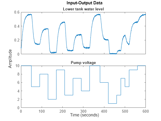
図 2: 2 タンク システムからの入出力データ
2 タンク システムのモデル化
次のステップは、2 タンク システムを記述するモデル構造を指定することです。このためには、x1(t) と x2(t) でそれぞれ上部タンクと下部タンクの水位を示します。各タンクについて、基礎的な物理特性 (質量バランス) から、水量の変化は流入と流出の差に依存します (i = 1、2)。
d/dt (Ai*xi(t)) = Qini(t) - Qouti(t)
ここで、Ai [m^2] はタンク i の断面積で、Qini(t) と Qouti(t) [m^3/s] は時刻 t におけるタンク i への流入とタンク i からの流出です。
上部タンクについて、流入はポンプに印加される電圧に比例すると仮定され、Qin1(t) = k*u(t) となります。上部タンクの排出孔は小さいため、Bernoulli の法則が適用され、流出は水位の平方根に比例します。正確には、次のようになります。
Qout1(t) = a1*sqrt(2*g*x1(t))
ここで a1 は排出孔の断面積で、g は重力定数です。下部タンクでは、流入量は上部タンクからの流出量と等しくなり (Qin2(t) = Qout1(t))、流出量は Bernoulli の法則によって与えられます。
Qout2(t) = a2*sqrt(2*g*x2(t))
ここで a2 は排出孔の断面積です。
これらの事実をまとめると、次の状態空間構造が得られます。
  d/dt x1(t) = 1/A1*(k*u(t) - a1*sqrt(2*g*x1(t)))
  d/dt x2(t) = 1/A2*(a1*sqrt(2*g*x1(t)) - a2*sqrt(2*g*x2(t)))
        y(t) = x2(t)
2 タンク C MEX モデル ファイル
次に、これらの方程式を、A1、k、a1、g、A2、a2 の 6 つのパラメーター (または定数) で C MEX ファイルに入力します。C MEX ファイルは通常、MATLAB® 言語を使用して作成したファイルよりも多少複雑ですが、C MEX モデリングは一般に、特に複雑なモデルの場合、実行速度において明白な利点があります。コード記述を支援するため、テンプレート C MEX ファイルが提供されています (以下を参照してください)。多くのアプリケーションの場合、いくつかの出力を定義して、dx と y をこのテンプレートに記述するコード行を入力するだけで十分です。IDNLGREY C MEX ファイルは、常に 2 つの出力を返すように構成してください。
  dx: the right-hand side(s) of the state-space equation(s)
   y: the right-hand side(s) of the output equation(s)
また、次のように 3+Npo(+1) 入力引数を指定してください。
   t: the current time
   x: the state vector at time t ([] for static models)
   u: the input vector at time t ([] for time-series models)
   p1, p2, ..., pNpo: the individual parameters (which can be real
      scalars, column vectors or 2-dimensional matrices); Npo is here
      the number of parameter objects, which for models with scalar
      parameters coincide with the number of parameters Np
   FileArgument: optional inputs to the model file
この 2 タンク システムでは、6 つのスカラー パラメーターがあり、C MEX モデリング ファイルへの入力引数の数は 3+Npo = 3+6 = 9 になります。オプションの FileArgument がこのアプリケーションには使用されていないため、後続の 10 番目の引数は省略できます。
C MEX モデリング ファイルの作成は通常、4 つのステップで行われます。
  1. Inclusion of C-libraries and definitions of the number of outputs.
  2. Writing the function computing the right-hand side(s) of the state
     equation(s), compute_dx.
  3. Writing the function computing the right-hand side(s) of the output
     equation(s), compute_y.
  4. Writing the main interface function, which includes basic error
     checking functionality, code for creating and handling input and
     output arguments, and calls to compute_dx and compute_y.
Let us view the C MEX source file (except for some comments) for the two
tank system and based on this discuss these four items in some more
detail.
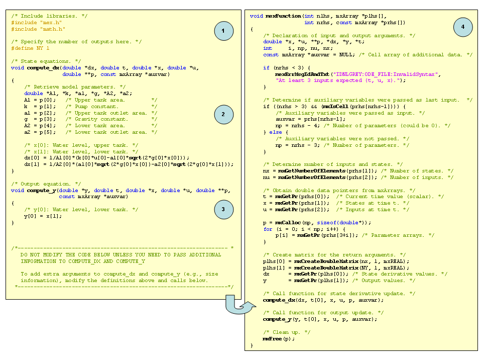
図 3: 2 タンク システムの C MEX ソース コード
1. mex.h と math.h の 2 つの C ライブラリが通常、MEX 関連の関数と数学関数にアクセスするために含まれています。出力の数も、標準 C 定義を使用してモデリング ファイルごとに宣言されます。
  /* Include libraries. */
  #include "mex.h"
  #include "math.h"
  /* Specify the number of outputs here. */
  #define NY 1
2-3.次に、ファイル内の状態を更新する関数 compute_dx と出力を更新する関数 compute_y を検討します。この関数は両方とも引数リストを保持し、計算する出力 (dx または y) が 1 番目の引数位置にあります。これに、状態方程式および出力方程式の右辺を計算するために必要なすべての変数とパラメーターが後続します。
これらの関数での最初のステップは、以降の方程式で使用されるモデル パラメーターを展開することです。有効な変数名 (入力引数リストで使用される変数を除く) を使用して、個々のパラメーターの物理的に意味のある名前を指定できます。
C の場合と同様に、配列の最初の要素は 0 の位置に格納されます。したがって、C での dx[0] は MATLAB の dx(1) (またはスカラーの場合は単に dx) に相当し、入力 u[0] は u (または u(1))、パラメーター A1[0] は A1 に相当します。
2 タンク モデル ファイルには、平方根の計算が含まれます。これは数学 C ライブラリ math.h を含めることで可能になります。数学ライブラリはよく使用される三角関数 (sin、cos、tan、asin、acos、atan など) 指数関数 (exp)、対数関数 (log、log10)、平方根 (sqrt)、べき乗 (pow)、絶対値の計算 (fabs) を実現します。math.h ライブラリは、math.h 関数が使用されている場合は常に含めなければなりません。それ以外の場合は、省略できます。FileArgument についての詳細は、「非線形グレー ボックス モデルの同定に関するチュートリアル: IDNLGREY モデル ファイルの作成」を参照してください。
4.メイン インターフェイス関数は、ほぼ常に同じ内容をもち、大半のアプリケーションについて変更は不要です。原則として、変更が必要と思われるのは、compute_dx および compute_y への呼び出しが行われる場合のみです。静的システムの場合は、compute_dx への呼び出しを省くことができます。その他の場合、状態方程式と出力方程式で参照される変数とパラメーターのみを渡すことを推奨します。たとえば、1 つの状態のみが使用される 2 タンク システムの出力方程式では、入力引数リストを次のように短縮できます。
void compute_y(double *y, double *x)
また、次のようにして compute_y を呼び出します。
compute_y(y, x);
compute_dx と compute_y の入力引数リストを拡張して、状態の数やパラメーターの数など、インターフェイス関数で参照されるその他の変数を含めることもできます。
モデル ソース ファイルが完成したら、コンパイルしなければなりません。これは mex コマンドを使用して MATLAB コマンド プロンプトから実行できます。「help mex」を参照してください (このステップはここでは省略します)。
モデル固有の C MEX ファイルを作成する場合、IDNLGREY C MEX テンプレート ファイルをコピーして作業を開始すると便利な場合があります。このテンプレートには、スケルトン ソース コードと、特定のアプリケーション向けにコードをカスタマイズするための詳細な手順が含まれています。
type IDNLGREY_MODEL_TEMPLATE.c/* Copyright 2005-2006 The MathWorks, Inc. */
/* Template file for IDNLGREY model specification.
Use this file to create a MEX function that specifies the model
structure and equations. The MEX file syntax is
[dx, y] = mymodel(t, x, u, p1, p2, ..., pn, auxvar)
where
* t is the time (scalar).
* x is the state vector at time t (column vector).
* u is the vector of inputs at time t (column vector).
* p1, p2,... pn: values of the estimated parameters specified
in the IDNLGREY model.
* auxvar: a cell array containing auxiliary data in any format
(optional).
* dx is the vector of state derivatives at time t (column vector).
* y is the vector of outputs at time t.
To create the MEX file "mymodel", do the following:
1) Save this template as "mymodel.c" (replace "mymodel" by the
name of your choice).
2) Define the number NY of outputs below.
3) Specify the state derivative equations in COMPUTE_DX below.
4) Specify the output equations in COMPUTE_Y below.
5) Build the MEX file using
>> mex mymodel.c
*/
/* Include libraries. */
#include "mex.h"
#include "math.h"
/* Specify the number of outputs here. */
#define NY 2
/* State equations. */
void compute_dx(
double *dx, /* Vector of state derivatives (length nx). */
double t, /* Time t (scalar). */
double *x, /* State vector (length nx). */
double *u, /* Input vector (length nu). */
double **p, /* p[j] points to the j-th estimated model parameters (a double array). */
const mxArray *auxvar /* Cell array of additional data. */
)
{
/*
Define the state equation dx = f(t, x, u, p[0],..., p[np-1], auvar)
in the body of this function.
*/
/*
Accessing the contents of auxvar:
Use mxGetCell to fetch pointers to individual cell elements, e.g.:
mxArray* auxvar1 = mxGetCell(auxvar, 0);
extracts the first cell element. If this element contains double
data, you may obtain a pointer to the double array using mxGetPr:
double *auxData = mxGetPr(auxvar1);
See MATLAB documentation on External Interfaces for more information
about functions that manipulate mxArrays.
*/
/* Example code from ODE function for DCMOTOR example
used in idnlgreydemo1 (dcmotor_c.c) follows.
*/
double *tau, *k; /* Estimated model parameters. */
tau = p[0];
k = p[1];
dx[0] = x[1]; /* x[0]: Angular position. */
dx[1] = -(1/tau[0])*x[1]+(k[0]/tau[0])*u[0]; /* x[1]: Angular velocity. */
}
/* Output equations. */
void compute_y(
double *y, /* Vector of outputs (length NY). */
double t, /* Time t (scalar). */
double *x, /* State vector (length nx). */
double *u, /* Input vector (length nu). */
double **p, /* p[j] points to the j-th estimated model parameters (a double array). */
const mxArray *auxvar /* Cell array of additional data. */
)
{
/*
Define the output equation y = h(t, x, u, p[0],..., p[np-1], auvar)
in the body of this function.
*/
/*
Accessing the contents of auxvar: see the discussion in compute_dx.
*/
/* Example code from ODE function for DCMOTOR example
used in idnlgreydemo1 (dcmotor_c.c) follows.
*/
y[0] = x[0]; /* y[0]: Angular position. */
y[1] = x[1]; /* y[1]: Angular velocity. */
}
/*----------------------------------------------------------------------- *
DO NOT MODIFY THE CODE BELOW UNLESS YOU NEED TO PASS ADDITIONAL
INFORMATION TO COMPUTE_DX AND COMPUTE_Y
To add extra arguments to compute_dx and compute_y (e.g., size
information), modify the definitions above and calls below.
*-----------------------------------------------------------------------*/
void mexFunction(int nlhs, mxArray *plhs[],
int nrhs, const mxArray *prhs[])
{
/* Declaration of input and output arguments. */
double *x, *u, **p, *dx, *y, *t;
int i, np, nu, nx;
const mxArray *auxvar = NULL; /* Cell array of additional data. */
if (nrhs < 3) {
mexErrMsgIdAndTxt("IDNLGREY:ODE_FILE:InvalidSyntax",
"At least 3 inputs expected (t, u, x).");
}
/* Determine if auxiliary variables were passed as last input. */
if ((nrhs > 3) && (mxIsCell(prhs[nrhs-1]))) {
/* Auxiliary variables were passed as input. */
auxvar = prhs[nrhs-1];
np = nrhs - 4; /* Number of parameters (could be 0). */
} else {
/* Auxiliary variables were not passed. */
np = nrhs - 3; /* Number of parameters. */
}
/* Determine number of inputs and states. */
nx = mxGetNumberOfElements(prhs[1]); /* Number of states. */
nu = mxGetNumberOfElements(prhs[2]); /* Number of inputs. */
/* Obtain double data pointers from mxArrays. */
t = mxGetPr(prhs[0]); /* Current time value (scalar). */
x = mxGetPr(prhs[1]); /* States at time t. */
u = mxGetPr(prhs[2]); /* Inputs at time t. */
p = mxCalloc(np, sizeof(double*));
for (i = 0; i < np; i++) {
p[i] = mxGetPr(prhs[3+i]); /* Parameter arrays. */
}
/* Create matrix for the return arguments. */
plhs[0] = mxCreateDoubleMatrix(nx, 1, mxREAL);
plhs[1] = mxCreateDoubleMatrix(NY, 1, mxREAL);
dx = mxGetPr(plhs[0]); /* State derivative values. */
y = mxGetPr(plhs[1]); /* Output values. */
/*
Call the state and output update functions.
Note: You may also pass other inputs that you might need,
such as number of states (nx) and number of parameters (np).
You may also omit unused inputs (such as auxvar).
For example, you may want to use orders nx and nu, but not time (t)
or auxiliary data (auxvar). You may write these functions as:
compute_dx(dx, nx, nu, x, u, p);
compute_y(y, nx, nu, x, u, p);
*/
/* Call function for state derivative update. */
compute_dx(dx, t[0], x, u, p, auxvar);
/* Call function for output update. */
compute_y(y, t[0], x, u, p, auxvar);
/* Clean up. */
mxFree(p);
}
IDNLGREY C MEX モデル ファイルの詳細については、「IDNLGREY モデル ファイルの作成」の例も参照してください。
2 タンク IDNLGREY モデル オブジェクトの作成
次のステップは、2 タンク システムを記述する IDNLGREY オブジェクトを作成することです。便宜上、入力と出力に関する記録情報も設定します (名前と単位)。
FileName      = 'twotanks_c';          % File describing the model structure.
Order         = [1 1 2];               % Model orders [ny nu nx].
Parameters    = {0.5; 0.0035; 0.019; ...
                 9.81; 0.25; 0.016};   % Initial parameters.
InitialStates = [0; 0.1];              % Initial value of initial states.
Ts            = 0;                     % Time-continuous system.
nlgr = idnlgrey(FileName, Order, Parameters, InitialStates, Ts, ...
                'Name', 'Two tanks');
set(nlgr, 'InputName', 'Pump voltage', 'InputUnit', 'V',             ...
          'OutputName', 'Lower tank water level', 'OutputUnit', 'm', ...                          ...
          'TimeUnit', 's');
状態の名前と単位とモデル パラメーターに関する情報を、SETINIT および SETPAR コマンドで追加していきます。さらに、状態 x1(t) と x2(t) の両方は負に設定できないタンク水位であるため、'Minimum' プロパティで x1(0) および x2(0) が 0 以上であることも指定します。実際、すべてのモデル パラメーターはゼロより大きくなければいけないことがわかっています。そこで、すべてのパラメーターの 'Minimum' プロパティをある小さな正数 (eps(0)) に設定します。これらの設定により、推定値に関する制約が以降の推定ステップで実行されることになります (推定されたモデルは、すべての入力された制約が適用されるモデルになります)。
nlgr = setinit(nlgr, 'Name', {'Upper tank water level' 'Lower tank water level'});
nlgr = setinit(nlgr, 'Unit', {'m' 'm'});
nlgr = setinit(nlgr, 'Minimum', {0 0});   % Positive levels!
nlgr = setpar(nlgr, 'Name', {'Upper tank area'        ...
                      'Pump constant'          ...
                      'Upper tank outlet area' ...
                      'Gravity constant'       ...
                      'Lower tank area'        ...
                      'Lower tank outlet area'});
nlgr = setpar(nlgr, 'Unit', {'m^2' 'm^3/(s*V)' 'm^2'  'm/(s^2)' 'm^2' 'm^2'});
nlgr = setpar(nlgr, 'Minimum', num2cell(eps(0)*ones(6,1)));   % All parameters > 0!
2 つのタンクの断面積 (A1 と A2) は、より正確に判定できます。したがって、これらと g を定数として取り扱い、'Fixed' フィールドがすべての 6 つのパラメーターに対してコマンド GETPAR で適切に設定されていることを確認します。これらすべてによって、モデル パラメーターのうち 3 つが推定されます。
nlgr.Parameters(1).Fixed = true;
nlgr.Parameters(4).Fixed = true;
nlgr.Parameters(5).Fixed = true;
getpar(nlgr, 'Fixed')ans=6×1 cell array
{[1]}
{[0]}
{[0]}
{[1]}
{[1]}
{[0]}
初期 2 タンク モデルの性能
自由パラメーター k、a1、a2 を推定する前に、初期パラメーター値を使用してシステムをシミュレートします。既定の微分方程式ソルバー (適応ステップ長を調整した Runge-Kutta 45 ソルバー) を使用して、絶対的および相対的許容誤差を小さな値に設定します (それぞれ 1e-6 と 1e-5)。COMPARE コマンドは、2 つの入力引数で呼び出されると、どの初期状態が 'Fixed' に定義されていても、既定の設定ですべての初期状態を推定することに注意してください。自由な初期状態のみを推定するためには、3 番目と 4 番目の入力引数を次のように指定して COMPARE を呼び出します。compare(z, nlgr, 'init', 'm')。タンク モデルの両方の初期状態は既定の設定では 'Fixed' であるため、このコマンドでは初期状態推定は実行されません。
nlgr.SimulationOptions.AbsTol = 1e-6;
nlgr.SimulationOptions.RelTol = 1e-5;

compare(z, nlgr);
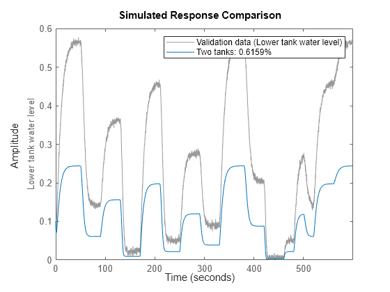
図 4: 初期 2 タンク モデルの実際の出力とシミュレーションの出力の比較
シミュレーションの出力と実際の出力がプロット ウィンドウに表示され、それほど一致していないことがわかります。
パラメーター推定
適合を高めるため、次に 3 つの自由パラメーターを NLGREYEST を使用して推定します (既定では、すべての初期状態の 'Fixed' フィールドは False なので、初期状態の推定は、推定器へのこの呼び出しでは実行されません)。
nlgr = nlgreyest(z, nlgr, nlgreyestOptions('Display', 'on'));
2 タンク推定モデルの性能
推定モデルの性能を調査するため、そのシミュレーションが実行されます (初期状態はここで再度推定されます)。
compare(z, nlgr);
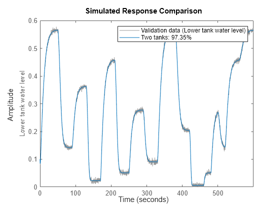
図 5: 推定 2 タンク モデルの実際の出力とシミュレーションの出力の比較
実際の出力とシミュレートした出力の適合は高くなっています。残りの疑問は、2 タンク システムをよりシンプルな線形モデル構造を使用して正確に記述できるかどうかということです。これに答えるため、データをある標準線形モデル構造に適合させ、COMPARE を使用してこれらのモデルがタンクのダイナミクスを適切に表現しているかを確認します。
nk = delayest(z);
arx22 = arx(z, [2 2 nk]);   % Second order linear ARX model.
arx33 = arx(z, [3 3 nk]);   % Third order linear ARX model.
arx44 = arx(z, [4 4 nk]);   % Fourth order linear ARX model.
oe22  = oe(z,  [2 2 nk]);   % Second order linear OE model.
oe33  = oe(z,  [3 3 nk]);   % Third order linear OE model.
oe44  = oe(z,  [4 4 nk]);   % Fourth order linear OE model.
sslin = ssest(z);           % State-space model (order determined automatically)
compare(z, nlgr, 'b', arx22, 'm-', arx33, 'm:', arx44, 'm--', ...
        oe22, 'g-', oe33, 'g:', oe44, 'g--', sslin, 'r-');
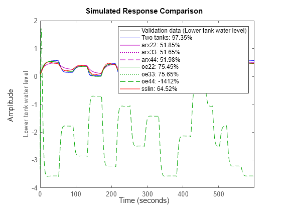
図 6: 複数の推定された 2 タンク モデルの実際の出力とシミュレーションの出力の比較
比較プロットでは、線形モデルは 2 タンク システムのすべてのダイナミクスを取得することはできないことが、明確にわかります。一方で、推定された非線形 IDNLGREY モデルは、実際の出力と非常によく一致しています。さらに、IDNLGREY モデル パラメーターも実際の出力の生成に使用されたパラメーターと一致しています。IDNLGREY オブジェクトのモデル パラメーターを格納する構造体配列からパラメーター ベクトルを返すコマンド GETPVEC を使用して、表示を行います。
disp(' True Estimated parameter vector');True Estimated parameter vector
ptrue = [0.5; 0.005; 0.02; 9.81; 0.25; 0.015];
fprintf('   %1.4f    %1.4f\n', [ptrue'; getpvec(nlgr)']);
0.5000 0.5000 0.0050 0.0049 0.0200 0.0200 9.8100 9.8100 0.2500 0.2500 0.0150 0.0147
PE を使用して取得された予測誤差は小さく、ランダム ノイズと非常によく似ています。
figure;
pe(z, nlgr);
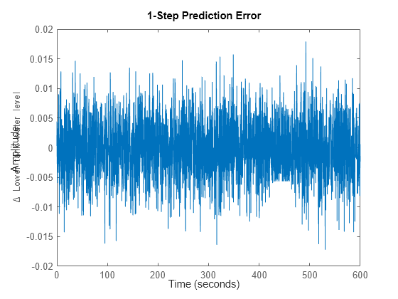
図 7: IDNLGREY 2 タンク モデルの推定モデルに取得した予測誤差
入力電圧が 5 から 6、7、8、9、10 V に段階的に増加した場合にどうなるかも調べてみます。この作業を行うには、5 ボルトの固定オフセットから順番に複数のステップ振幅を指定して STEP を呼び出します。stepDataOptions で作成された専用のオプションセットを使用すると、ステップ応答の構成が簡単になります。
figure('Name', [nlgr.Name ': step responses']);
t = (-20:0.1:80)';
Opt = stepDataOptions('InputOffset',5,'StepAmplitude',6);
step(nlgr, t, 'b', Opt);
hold on

Opt.StepAmplitude = 7;  step(nlgr, t, 'g', Opt);
Opt.StepAmplitude = 8;  step(nlgr, t, 'r', Opt);
Opt.StepAmplitude = 9;  step(nlgr, t, 'm', Opt);
Opt.StepAmplitude = 10; step(nlgr, t, 'k', Opt);

grid on;
legend('5 -> 6 V', '5 -> 7 V', '5 -> 8 V', '5 -> 9 V', '5 -> 10 V', ...
       'Location', 'Best');
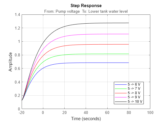
図 8: IDNLGREY 2 タンク モデルの推定モデルに取得したステップ応答
最後に、PRESENT コマンドを使用して、推定モデルの概要情報を取得します。
present(nlgr);
nlgr =

Continuous-time nonlinear grey-box model defined by 'twotanks_c' (MEX-file):

   dx/dt = F(t, u(t), x(t), p1, ..., p6)
    y(t) = H(t, u(t), x(t), p1, ..., p6) + e(t)

 with 1 input(s), 2 state(s), 1 output(s), and 3 free parameter(s) (out of 6).

 Inputs:
    u(1)  Pump voltage(t) [V]
 States:                                Initial value
    x(1)  Upper tank water level(t) [m]   xinit@exp1     0   (fixed) in [0, Inf]
    x(2)  Lower tank water level(t) [m]   xinit@exp1   0.1   (fixed) in [0, Inf]
 Outputs:
    y(1)  Lower tank water level(t) [m]
 Parameters:                             Value   Standard Deviation
    p1   Upper tank area [m^2]                   0.5              0   (fixed) in ]0, Inf]
    p2   Pump constant [m^3/(s*V)]        0.00488584      0.0259032   (estimated) in ]0, Inf]
    p3   Upper tank outlet area [m^2]      0.0199719      0.0064682   (estimated) in ]0, Inf]
    p4   Gravity constant [m/(s^2)]             9.81              0   (fixed) in ]0, Inf]
    p5   Lower tank area [m^2]                  0.25              0   (fixed) in ]0, Inf]
    p6   Lower tank outlet area [m^2]      0.0146546      0.0776058   (estimated) in ]0, Inf]

Name: Two tanks

Status:
Termination condition: Change in cost was less than the specified tolerance..
Number of iterations: 8, Number of function evaluations: 9

Estimated using Solver: ode45; Search: lsqnonlin on time domain data "Two tanks".
Fit to estimation data: 97.35%
FPE: 2.419e-05, MSE: 2.414e-05
More information in model's "Report" property.

Model Properties
まとめ
この例では、次の内容について説明しました。
  1. how to use C MEX-files for IDNLGREY modeling, and
  2. provided a rather simple example where nonlinear state-space
     modeling shows good potential