GroundSurface
Description
The GroundSurface object defines a ground
surface object belonging to a trackingScenario
object. You can use the GroundSurface object to model
terrain in a scenario and query the occlusion status of line-of-sight between two points in
the scenario.
Creation
Create GroundSurface objects using the groundSurface
object function of the trackingScenario
object.
Properties
Object Functions
Examples
Create a mesh grid that spans from -1000 meters to 1000 meters in both the x- and y-directions.
[x,y] = meshgrid(linspace(-1000,1000,500));
Specify the height for each mesh grid point.
z = 200*cos(x*pi/2000).*cos(y*pi/2000);
Create a tracking scenario and add a ground surface object to the tracking scenario. Specify the boundary of the surface area.
scene = trackingScenario;
surface = groundSurface(scene,Terrain=z,Boundary=[-1e3 1e3; -1e3 1e3])
surface =
  GroundSurface with properties:

            Terrain: [500×500 double]
    ReferenceHeight: 0
           Boundary: [2×2 double]
Note that the SurfaceManager property of the tracking scenario now contains the created GroundSurface object.
manager = scene.SurfaceManager
manager =
  SurfaceManager with properties:

    UseOcclusion: 1
        Surfaces: [1×1 fusion.scenario.GroundSurface]
manager.Surfaces
ans =
  GroundSurface with properties:

            Terrain: [500×500 double]
    ReferenceHeight: 0
           Boundary: [2×2 double]
Visualize the surface using the helperGetTerrainMap helper function, attached to this example.
xSamples = linspace(-1e3,1e3,100);
ySamples = linspace(-1e3,1e3,100);
helperGetTerrainMap(surface,xSamples,ySamples);
xlabel("x (m)")
ylabel("y (m)")
zlabel("Height (m)")
![]()
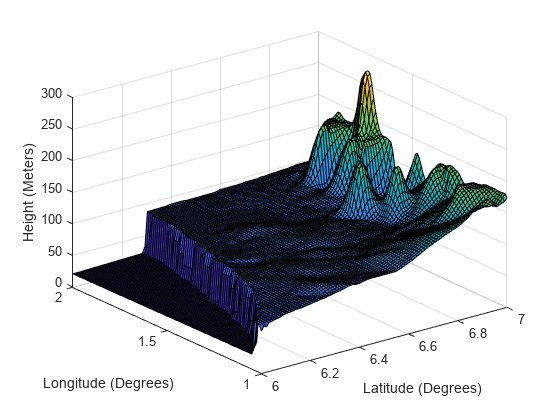
Create a tracking scenario and specify its IsEarthCentered property as true.
scene = trackingScenario(IsEarthCentered=true);
Add a ground surface based on a DTED file, covering from 6 to 7 degrees in latitude and from 1 to 2 degrees in longitude.
terrain = "n06.dt0";
boundary = [6 7; % Latitude in degrees
            1 2]; % Longitude in degrees
surface = groundSurface(scene,Terrain=terrain,Boundary=boundary);
Sample the area using a 100-by-100 grid map.
samples = 100;
latitudes = linspace(6,7,samples);
longitudes = linspace(1,2,samples);
positions = [latitudes; longitudes];
Plot the terrain using the helperGetTerrrainMap helper function, attached to this example.
helperGetTerrainMap(surface,latitudes,longitudes);
xlabel("Latitude (Degrees)");
ylabel("Longitude (Degrees)");
zlabel("Height (Meters)");
Create a tracking scenario object.
scene = trackingScenario;
Specify the terrain as magic(4) and define the boundary of the terrain as a square.
terrain = magic(4)
terrain = 4×4

    16     2     3    13
     5    11    10     8
     9     7     6    12
     4    14    15     1
boundary = [0 100; 0 100];
Create the ground surface and add it to the scenario.
surface = groundSurface(scene,Terrain=terrain,Boundary=boundary)
surface =
  GroundSurface with properties:

            Terrain: [4×4 double]
    ReferenceHeight: 0
           Boundary: [2×2 double]
Get the heights of the surface at the center and its four corners.
h0 = height(surface,[50 50]')
h0 =
8.5000
h1 = height(surface,[0 0]')
h1 =
16
h2 = height(surface,[100 0]')
h2 =
13
h3 = height(surface,[0 100]')
h3 =
4
h4 = height(surface,[100 100]')
h4 =
1
Create a tracking scenario object.
scene = trackingScenario;
Specify the terrain and define the boundary of the terrain as a square centered at the origin.
terrrain =[0 10 0;
           0 10 0;
           0 10 0];
boundary = [-100 100; -100 100];
Create the ground surface and add it to the scenario.
surface = groundSurface(scene,Terrain=terrrain,Boundary=boundary)
surface =
  GroundSurface with properties:

            Terrain: [3×3 double]
    ReferenceHeight: 0
           Boundary: [2×2 double]
Query the occlusion status of the line-of-sight vector between the corner point (–100, –100, 0) and the other corner point (100, 100, 20). The ground surface occludes the line-of-sight.
occlusion(surface,[-100 -100 0],[100 100 20])
ans = logical
   0
Raise the height of the first corner point. Now the ground surface no longer occludes the line-of-sight.
occlusion(surface,[-100 -100 10],[100 100 20])
ans = logical
   0
Version History
Introduced in R2022a