for ループ
この例では、Simulink® ブロック、Stateflow® チャート、および MATLAB® Function ブロックを使用して for ループ構造を実装する方法を示します。
C 構成要素
y1 = 0;
for(inx = 0; inx <10; inx++)
{
  y1 = u1[inx] + y1;
}
for ループのモデル化パターン: For Iterator Subsystem ブロック
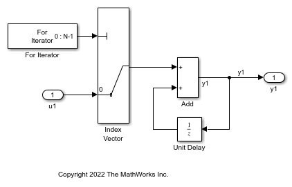
for ループを作成する方法の 1 つとして、[Simulink]、[Ports and Subsystems] ライブラリの For Iterator Subsystem ブロックを使用する方法があります。
1. モデル例 ex_for_loop_SL を開きます。

モデルには、シミュレーションのタイム ステップでサブシステムの内容の実行を繰り返す For Iterator Subsystem ブロックが含まれています。

モデルで次の設定を確認します。
For Iterator ブロックを開きます。[ブロック パラメーター] ダイアログ ボックスで、[インデックス モード] パラメーターが
Zero-based、[反復制限] パラメーターが 10 になっています。Unit Delay ブロックを開きます。[ブロック パラメーター] ダイアログ ボックスで、[初期条件] パラメーターが 0 になっています。このパラメーターで状態がゼロに初期化されます。
2. モデルをビルドしてコードを生成するには、Ctrl+B を押します。
for ループを実装するコードが ex_for_loop_SL.c の関数 ex_for_loop_SL_step に含まれています。
/* External inputs (root inport signals with default storage) */
ExternalInputs U;

/* External outputs (root outports fed by signals with default storage) */
ExternalOutputs Y;

/* Model step function */
void ex_for_loop_SL_step(void)
{
  int32_T rtb_y1;
  int32_T s1_iter;

  /* Outputs for Iterator SubSystem: '<Root>/For Iterator Subsystem' incorporates:
   *  ForIterator: '<S1>/For Iterator'
   */
  for (s1_iter = 0; s1_iter < 10; s1_iter++) {
    /* Sum: '<S1>/Add' incorporates:
     *  Inport: '<Root>/u1'
     *  MultiPortSwitch: '<S1>/Index Vector'
     *  UnitDelay: '<S1>/Unit Delay'
     */
    rtb_y1 = U.u1[s1_iter] + DWork.UnitDelay_DSTATE;

    /* Update for UnitDelay: '<S1>/Unit Delay' */
    DWork.UnitDelay_DSTATE = rtb_y1;
  }

  /* End of Outputs for SubSystem: '<Root>/For Iterator Subsystem' */

  /* Outport: '<Root>/y1' */
  Y.y1 = rtb_y1;
}
for ループのモデル化パターン: Stateflow チャート
1. モデル例 ex_for_loop_SF を開きます。

チャートには For ループの判定パターンが含まれています。これは、チャート内で右クリックし、[パターンをチャートに追加]、[ループ]、[For] を選択して追加します。
2. モデルをビルドしてコードを生成するには、Ctrl+B を押します。
for ループを実装するコードが ex_for_loop_SF.c の関数 ex_for_loop_SF_step に含まれています。
/* External inputs (root inport signals with default storage) */
ExternalInputs U;

/* External outputs (root outports fed by signals with default storage) */
ExternalOutputs Y;

/* Model step function */
void ex_for_loop_SF_step(void)
{
  int32_T inx;

  /* Chart: '<Root>/Chart' */
  for (inx = 0; inx < 10; inx++) {
    /* Outport: '<Root>/y1' incorporates:
     *  Inport: '<Root>/u1'
     */
    Y.y1 += U.u1[inx];
  }

  /* End of Chart: '<Root>/Chart' */
}
for ループのモデル化パターン: MATLAB Function ブロック
1. モデル例 ex_for_loop_ML を開きます。

MATLAB Function ブロックには次の関数が含まれています。
function y1 = fcn(u1)

y1 = 0;

for inx=1:10
    y1 = u1(inx) + y1 ;
end
2. モデルをビルドしてコードを生成するには、Ctrl+B を押します。
for ループを実装するコードが ex_for_loop_ML.c の関数 ex_for_loop_ML_step に含まれています。
/* Exported block signals */
real_T u1[10];                         /* '<Root>/u1' */
real_T y1;                             /* '<Root>/MATLAB Function' */

/* Model step function */
void ex_for_loop_ML_step(void)
{
  int32_T inx;

  /* MATLAB Function: '<Root>/MATLAB Function' incorporates:
   *  Inport: '<Root>/u1'
   */
  y1 = 0.0;
  for (inx = 0; inx < 10; inx++) {
    y1 += u1[inx];
  }

  /* End of MATLAB Function: '<Root>/MATLAB Function' */
}