MCAN Receive Peripheral Configuration
Map MCAN Receive peripherals in the model to the peripheral registers in MCU
Since R2024b
Description
Add-On Required: This feature requires the Embedded Coder Support Package for Infineon AURIX TC4x Microcontrollers add-on.
Use the Hardware Mapping tool to view and edit the module and node settings of MCAN peripherals in the Infineon® AURIX™ model.
Using the Hardware Mapping tool, you can:
View and edit the configuration parameters of the MCAN Receive block.
Check for any conflicts between the peripherals.
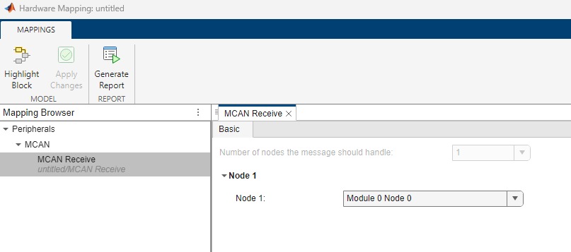
Open the MCAN Receive Peripheral Configuration
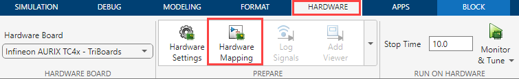
In the Hardware tab of the Simulink® model, click Model Settings to open the Configuration Parameters dialog box. Click on Hardware Implementation in the left pane and set Hardware board parameter to
Infineon AURIX TC4x - TriBoards.In the Hardware tab of the Simulink model, click Hardware Mapping. In the Mapping Browser pane, navigate to Peripherals > MCAN > MCAN Transmit to configure MCAN transmission nodes.
Examples
Parameters
Global parameters > Module # Node #
Select the pin number for CAN message transmission.
Select the pin number for CAN message reception.
Select the strength of the output pins for CAN communication.
Select the input mode for the CAN communication.
Select the speed of the CAN transmit and receive pins.
Select the voltage level of the CAN transmit and receive pins.
Select the frame format for CAN communication.
Select this parameter to enable calculate the bit timing automatically.
Select to enable bit rate switching between nominal bit rate and data bit rate.
Dependencies
To enable this parameter, set the Frame format
parameter to CAN-FD.
Global parameters > Module # Node # > Arbitration phase parameters
Specify the baud rate for the selected CAN node in the arbitration phase.
Dependencies
To enable this parameter, set the Frame format
parameter to CAN-FD and select the Enable
bit rate switching parameter.
Specify the sample point to synchronize the CAN nodes in the arbitration phase.
Dependencies
To enable this parameter, set the Frame format
parameter to CAN-FD, select the Enable bit
rate switching parameter, and select the Auto calculate
bit timing parameter.
Specify the number of bit time quanta to compensate the edge phase errors before the sampling point. Typically, an adjustment of this value is made with a corresponding inverse adjustment to the Time segment 2 parameter, such that their sum remains constant.
Dependencies
To enable this parameter, set the Frame format
parameter to CAN-FD, select the Enable bit
rate switching parameter, and disable the Auto
calculate bit timing parameter.
Specify the number of bit time quanta to compensate the edge phase errors after the sampling point. Typically, an adjustment of this value is made with a corresponding inverse adjustment to the Time segment 1 parameter, such that their sum remains constant.
Dependencies
To enable this parameter, set the Frame format
parameter to CAN-FD, select the Enable bit
rate switching parameter, and disable the Auto
calculate bit timing parameter.
Specify the bit time adjustment limit for the arbitration phase. Specify a positive integer indicating the number of bit time quanta segments.
Dependencies
To enable this parameter, set the Frame format
parameter to CAN-FD, select the Enable bit
rate switching parameter, and disable the Auto
calculate bit timing parameter.
Global parameters > Module # Node # > Data phase parameters
Specify the baud rate of data.
Dependencies
To enable this parameter, set the Frame format
parameter to CAN-FD and select the Enable
bit rate switching parameter.
Specify the percentage of the bit time to sample the bit for CAN transmission.
Dependencies
To enable this parameter, set the Frame format
parameter to CAN-FD, select the Enable bit
rate switching parameter, and select the Auto calculate
bit timing parameter.
Specify the number of bit time quanta before the sampling point. Typically, an adjustment of this value is made with a corresponding inverse adjustment to the Time segment 2 parameter, such that their sum remains constant.
Dependencies
To enable this parameter, set the Frame format
parameter to CAN-FD, select the Enable bit
rate switching parameter, and disable the Auto
calculate bit timing parameter.
Specify the number of bit time quanta after the sampling point. Typically, an adjustment of this value is made with a corresponding inverse adjustment to the Time segment 1 parameter, such that their sum remains constant.
Dependencies
To enable this parameter, set the Frame format
parameter to CAN-FD, select the Enable bit
rate switching parameter, and disable the Auto
calculate bit timing parameter.
Specify the maximum limit of bit time adjustment in the case of resynchronization in the data phase. The specified value must be a positive integer indicating a number of bit time quanta segments.
Dependencies
To enable this parameter, set the Frame format
parameter to CAN-FD, select the Enable bit
rate switching parameter, and disable the Auto
calculate bit timing parameter.
Select to enable transceiver delay.
Dependencies
To enable this parameter, set the Frame format
parameter to CAN-FD and select the Enable
bit rate switching parameter.
Specify the percentage of the bit time for re-sampling the bit after the transceiver delay to avoid bit errors.
Dependencies
To enable this parameter, set the Frame format
parameter to CAN-FD, enable the Auto
calculate bit timing, and the Enable transceiver
delay parameters.
Specify transceiver delay compensation offset in MCAN clock ticks to achieve higher baud rates for data phase of a CAN-FD frame.
Dependencies
To enable this parameter, set the Frame format
parameter to CAN-FD, disable the Auto
calculate bit timing, select the Enable bit rate
switching parameter, and the Enable transceiver
delay parameters.
Global parameters > Module # Node # > Bus parameters
Specify the baud rate for the CAN bus.
Dependencies
To enable this parameter, set the Frame format
parameter to Classic CAN.
Specify the sample point to synchronize the CAN nodes.
Dependencies
To enable this parameter, set the Frame format
parameter to Classic CAN and enable the
Auto calculate bit timing parameter.
Specify the number of bit time quanta before the sampling point. Typically, an adjustment of this value is made with a corresponding inverse adjustment to the Time segment 2 parameter, such that their sum remains constant.
Dependencies
To enable this parameter, set the Frame format
parameter to Classic CAN and disable the
Auto calculate bit timing parameters.
Specify the number of bit time quanta after the sampling point. Typically, an adjustment of this value is made with a corresponding inverse adjustment to the Time segment 1 parameter, such that their sum remains constant.
Dependencies
To enable this parameter, set the Frame format
parameter to Classic CAN and disable the
Auto calculate bit timing parameters.
Specify the maximum limit of bit time adjustment in the case of resynchronization. The specified value must be a positive integer indicating a number of bit time quanta segments.
Dependencies
To enable this parameter, set the Frame format
parameter to Classic CAN and disable the
Auto calculate bit timing parameters.
Global parameters > Module # Node # > Transmit
Specify the transmission mode for CAN communication.
Specify Individual data field size for CAN data transmission.
Specify the number of dedicated buffers for CAN data transmission.
Dependencies
To enable this parameter, set the Transmit mode
parameter to Dedicated-Buffers and FIFO,
Dedicated-Buffers, or
Dedicated-Buffers
                        and Queue
.
Specify the number of queue elements for CAN data transmission.
Dependencies
To enable this parameter, set the Transmit mode
parameter to Queue or Dedicated-Buffers
and Queue.
Specify the number of FIFO registers for CAN data transmission.
Dependencies
To enable this parameter, set the Transmit mode
parameter to FIFO or Dedicated-Buffers
and FIFO.
This parameter is read-only. You can calculate the occupied RAM memory in bytes by using this formula:(Individual data field size + 8) x (Number of dedicated buffers + Number of FIFO+Number of Queue).
Global parameters > Module # Node # > Receive
Specify the mode to receive CAN data.
Configure the parameters and interrupts corresponding to FIFO registers or
buffers based on the value of Receive mode parameter. For
example, set this parameter to Dedicated-Buffers and FIFO 0 and FIFO
1 to configure interrupts and parameters related to FIFO 0, FIFO
1 registers, and buffers.
Specify the individual data field size for CAN data reception.
Dependencies
To enable this parameter, set the Receive mode
parameter to Dedicated-Buffers and FIFO 0 and FIFO
1, Dedicated-Buffers and FIFO 0,
Dedicated-Buffers and FIFO 1, or
Dedicated-Buffers.
This parameter is read-only. You can calculate the occupied RAM memory occupied in bytes by using this formula: (Individual data field size + 8) x (Number of buffers + Number of FIFO elements).
Note
If you configure Receive mode without dedicated buffers
such as FIFO 0 or FIFO 1,
Simulink allocates 512 bytes of RAM memory for the buffers used in CAN
reception.
Global parameters > Module # Node # > FIFO #
Specify the individual data field size of FIFO # register for CAN data reception.
Dependencies
To enable this parameter, set the Receive mode
parameter to Dedicated-Buffers and FIFO 0 and FIFO
1, Dedicated-Buffers and FIFO #, or
FIFO #.
Specify the mode of operation of FIFO # registers for CAN data reception.
Dependencies
To enable this parameter, set the Receive mode
parameter to Dedicated-Buffers and FIFO 0 and FIFO
1, Dedicated-Buffers and FIFO #, or
FIFO #.
Specify the number of FIFO elements for CAN data reception.
Dependencies
To enable this parameter, select the Receive mode
parameter to Dedicated-Buffers and FIFO 0 and FIFO
1, Dedicated-Buffers and FIFO #, or
FIFO #.
Specify the watermark level for CAN data reception
Note
The value of Watermark level parameter must be less than or equal to the Number of FIFO elements parameter value.
Dependencies
To enable this parameter, set the Receive mode
parameter to Dedicated-Buffers and FIFO 0 and FIFO
1, Dedicated-Buffers and FIFO #, or
FIFO #.
This is a read-only parameter and you can calculate RAM memory occupied in 8-bit bytes using this formula: (Individual data field size+8) x Number of FIFO elements.
Global parameters > Module # Node # > Filter
Enable this parameter so that the block rejects all remote frames with 11-bit standard IDs.
Enable this parameter so that the block rejects all remote frames with 29-bit extended IDs.
Specify whether to accept non-matching 11-bit standard ID frames in the FIFO register or reject them.
Specify whether to accept non-matching 29-bit extended ID frames in the FIFO register or reject them.
Specify a mask for the range filter.
Global parameters > Module # Node # > Standard filter
Select the standard filter element number.
The block uses all the specified filter elements for acceptance filtering of standard frames. Acceptance filtering stops when the block finds the matching filter element among the specified elements or when it reaches the end of the filter list.
Note
You can select any filter element and configure its parameters. You can view the configured filter elements in the read-only parameter Standard filters configured.
The filter numbers in the generated code differ from the standard filters configured in the Hardware Mapping tool because Simulink allocates filter numbers sequentially to optimize RAM memory during code generation.
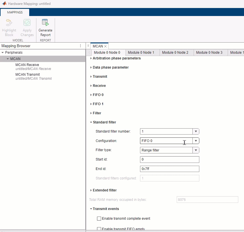
Select one of the following configuration options for the standard filter element specified in the Standard filter number parameter:
Disable— Disable the standard filter element.FIFO 0— Store in Rx FIFO 0 register if filter matches.FIFO 1— Store in Rx FIFO 1 register if filter matches.Reject— Reject ID if filter matches.High priority interrupt and reject— Set high priority interrupt and reject ID if filter matches.High priority interrupt-and-FIFO0— Set high priority interrupt and store in FIFO 0 if filter matches.High priority interrupt-and-FIFO1— Set high priority interrupt and store in FIFO 1 if filter matches.Buffers— Store in Rx Buffer.
Select the filter type for the standard filter element specified in the Standard filter number parameter.
Dependencies
To enable this parameter, set the Configuration
parameter to FIFO 0, FIFO
1, Reject, High
priority interrupt and reject, High priority
interrupt-and-FIFO0, or High priority
interrupt-and-FIFO1.
Specify the start ID for the range filter of the selected filter element in the Standard filter number parameter.
Dependencies
To enable this parameter, set the Filter type parameter
to Range filter.
Specify the end ID for the range filter of the selected filter element in the Standard filter number parameter.
Dependencies
To enable this parameter, set the Filter type parameter
to Range filter.
Specify ID 1 for the selected filter element in the Standard filter number parameter.
Dependencies
To enable this parameter, set the Filter type parameter
to Dual ID or Classic
mask.
Specify ID 2 for the selected filter element in the Standard filter number parameter.
Dependencies
To enable this parameter, set the Filter type parameter
to Dual ID.
Specify the mask for the selected filter element in the Standard filter number parameter.
The 0 bit masks the corresponding bit position of the configured message ID filter (ID 1) and the value of the received message ID at that bit position is not relevant for acceptance filtering. Only those bits of the received message ID where the corresponding mask bits equal to 1 are relevant for acceptance filtering.
For example, consider ID 1 as 0x201
(0x 0010 0000 0001 in binary) and Mask
as 0x7E0 (0x 0111 1110 0000 in binary). The
valid message IDs for this configuration are 0x x010 000x xxxx,
where x can be 0 or 1
representing a don't care condition.
Dependencies
To enable this parameter, set the Filter type parameter
to Classic mask.
Specify the buffer number for the selected filter element in the Standard filter number parameter.
Dependencies
To enable this parameter, set the Configuration
parameter to Buffers.
Global parameters > Module # Node # > Extended filter
Select the extended filter element number.
The block uses all the specified filter elements for acceptance filtering of standard frames. Acceptance filtering stops when the block finds the matching filter element among the specified elements or when it reaches the end of the filter list.
Note
You can select any filter element and configure its parameters. You can view the configured filter elements in the read-only parameter Extended filters configured.
The filter numbers in the generated code differ from the extended filters configured in the Hardware Mapping tool because Simulink allocates filter numbers sequentially to optimize RAM memory during code generation.
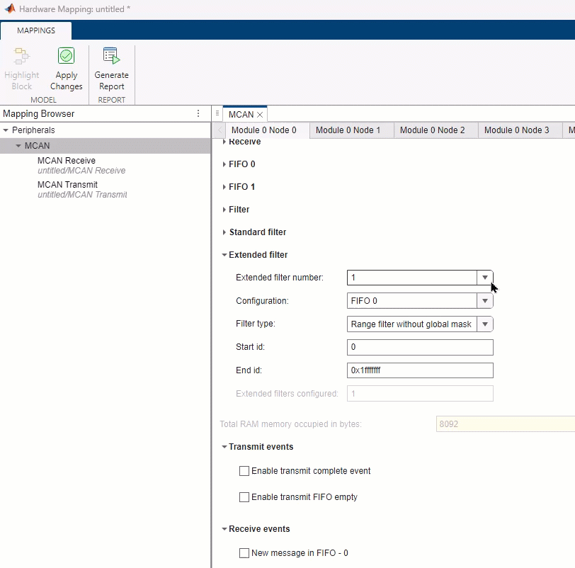
Select one of the following configuration options for the extended filter element selected using Extended filter number parameter:
Disable— Disable the extended filter element.FIFO 0— Store in Rx FIFO 0 register if filter matches.FIFO 1— Store in Rx FIFO 1 register if filter matches.Reject— Reject ID if filter matches.High priority interrupt and reject— Set high priority interrupt and reject ID if filter matches.High priority interrupt-and-FIFO0— Set high priority interrupt and store in FIFO 0 if filter matches.High priority interrupt-and-FIFO1— Set high priority interrupt and store in FIFO 1 if filter matches.Buffers— Store in Rx Buffer.
Select the filter type for the extended filter element selected using the Extended filter number parameter.
Note
If you set this parameter to Range filter with global
mask, the block performs a logical AND of the message ID of
the received extended ID frame and the Global mask for range
filter parameter value configured in Filter
tab. To ignore the mask, set the Global mask for range
filter parameter to 0x1fffffff.
Dependencies
To enable this parameter, set the Configuration
parameter to FIFO 0, FIFO
1, Reject, High
priority interrupt and reject, High priority
interrupt-and-FIFO0, or High priority
interrupt-and-FIFO1.
Specify the start ID for the range filter of the selected filter element in the Extended filter number parameter.
Dependencies
To enable this parameter, set the Filter type parameter
to Range filter.
Specify the end ID for the range filter of the selected filter element in the Extended filter number parameter.
Dependencies
To enable this parameter, set the Filter type parameter
to Range filter.
Specify ID 1 for the selected filter element in the Extended filter number parameter.
Dependencies
To enable this parameter, set the Filter type parameter
to Dual ID or Classic
mask.
Specify ID 2 for the selected filter element in the Extended filter number parameter.
Dependencies
To enable this parameter, set the Filter type parameter
to Dual ID.
Specify the mask for the selected filter element in the Extended filter number parameter.
The 0 bit masks the corresponding bit position of the configured message ID filter (ID 1) and the value of the received message ID at that bit position is not relevant for acceptance filtering. Only those bits of the received message ID where the corresponding mask bits equal to 1 are relevant for acceptance filtering.
For example, consider ID 1 as 0x201
(0x 0010 0000 0001 in binary) and Mask
as 0x7E0 (0x 0111 1110 0000 in binary). The
valid message IDs for this configuration are 0x x010 000x xxxx,
where x can be 0 or 1
representing a don't care condition.
Dependencies
To enable this parameter, set the Filter type parameter
to Classic mask.
Specify the buffer number for the selected filter element in the Extended filter number parameter.
Dependencies
To enable this parameter, set the Configuration
parameter to Buffers.
This parameter is read-only. It shows the total occupied RAM memory in bytes during transmission and reception of the CAN message.
Note
Each standard filter configuration occupies 8-bytes of RAM memory and each extended filter configuration occupies 2-bytes of RAM memory.
Global parameters > Module # Node # > Transmit events
Select this parameter to enable the interrupt for the transmit complete event.
Enable the interrupt to view the Interrupt service request
line parameter and specify Service
request-#.
Select this parameter to enable the interrupt for transmit FIFO empty event.
Enable the interrupt to view the Interrupt service request
line parameter and specify Service
request-#.
Dependencies
To enable this parameter, set the Transmit mode
parameter to Dedicated-Buffers and FIFO or
FIFO.
Global parameters > Module # Node # > Receive events
Select this parameter to enable the interrupt for a new message in FIFO - #.
Enable the interrupt to view the Interrupt service request
line parameter and specify Service
request-#.
Dependencies
To enable this parameter, set the Receive mode
parameter to Dedicated-Buffers and FIFO 0 and FIFO
1, Dedicated-Buffers and FIFO #, or
FIFO #.
Select this parameter to enable the interrupt for a FIFO - # full event.
Enable the interrupt to view Interrupt service request
line parameter and specify Service
request-#.
Dependencies
To enable this parameter, set the Receive mode
parameter to Dedicated-Buffers and FIFO 0 and FIFO
1, Dedicated-Buffers and FIFO #, or
FIFO #.
Select this parameter to enable the interrupt for message stored in the dedicated buffer.
Enable the interrupt to view the Interrupt service request
line parameter and specify Service
request-#.
Dependencies
To enable this parameter, set the Receive mode
parameter to Dedicated-Buffers and FIFO 0 and FIFO
1, Dedicated-Buffers and FIFO #, or
Dedicated-Buffers.
Select this parameter to enable the interrupt for a high priority message.
Enable the interrupt to view the Interrupt service request
line parameter and specify Service
request-#.
Dependencies
To enable this parameter, set the Configuration
parameter of any standard or extended filter to High priority
interrupt and reject, High priority
interrupt-and-FIFO0, or High priority
interrupt-and-FIFO1.
Global parameters > Module # Node # > Watermark event
Select this parameter to enable the interrupt for the watermark level of FIFO - #.
Enable the interrupt to view the Interrupt service request
line parameter and specify Service
request-#.
Dependencies
To enable this parameter, set the Receive mode
parameter to Dedicated-Buffers and FIFO 0 and FIFO
1, Dedicated-Buffers and FIFO #, or
FIFO #.
Global parameters > Module # Node # > Alert event
Select this parameter to enable the interrupt for a message lost in FIFO - #.
Enable the interrupt to view the Interrupt service request
line parameter and specify Service
request-#.
Dependencies
To enable this parameter, set the Receive mode
parameter to Dedicated-Buffers and FIFO 0 and FIFO
1, Dedicated-Buffers and FIFO #, or
FIFO #.
Select this parameter to enable the passive error interrupt.
Enable the interrupt to view the Interrupt service request
line parameter and specify Service
request-#.
Select this parameter to enable the waiting status interrupt.
Enable the interrupt to view the Interrupt service request
line parameter and specify Service
request-#.
Global parameters > Module # Node # > Protocol error event
Select this parameter to enable the protocol error arbitration interrupt.
Enable the interrupt to view the Interrupt service request
line parameter and specify Service
request-#.
Select this parameter to enable the protocol error data interrupt.
Enable the interrupt to view the Interrupt service request
line parameter and specify Service
request-#.
Global parameters > Module # Node # > Error events
Select this parameter to enable the bus off error interrupt.
Enable the interrupt to view the Interrupt service request
line parameter and specify Service
request-#.
Select to enable the watchdog event interrupt.
Enable the interrupt to view the Interrupt service request
line parameter and specify Service
request-#.
Basic > Node #
Specify the module and node for CAN data reception.
Version History
Introduced in R2024b