Create Signals for Frame-Based Processing
In frame-based processing, blocks and System objects process data in frames. Each frame of data contains samples of consecutive times stacked together. Each channel is represented by a column of the input signal. For example, from a frame-based processing perspective, this 3-by-2 matrix has two channels, each containing three samples.

When you configure a block to perform frame-based processing, the block interprets an M-by-1 vector as a single-channel signal containing M samples per frame. Similarly, the block interprets an M-by-N matrix as a multichannel signal with N independent channels and M samples per channel. For example, in frame-based processing, blocks interpret this sequence of 3-by-2 matrices as a two-channel signal with a frame size of 3.

Multichannel Signals for Frame-Based Processing
When you want to perform the same operations on several independent signals,
you can group the signals into a multichannel signal. For example, if you need
to filter each of four independent signals using the same direct-form II
transposed filter, you can combine the signals into a multichannel signal, and
connect the signal to a single Biquad Filter block. The block
treats each column of the input as a channel when you set the Input
processing parameter to Columns as channels (frame
based). The block then applies the filter to each channel
independently.
A matrix of size M-by-N represents a signal with N channels and frame size of M. You can combine multiple individual signals with the same frame rate and frame size into a single multichannel signal using the Simulink® Matrix Concatenate (Simulink) block. You can also add individual signals to an existing multichannel signal in the same way.
This topic discusses creating signals for frame-based processing using the Sine Wave and Signal From Workspace blocks. You can use a Matrix Concatenate block to combine these signals. The block receiving the signal implements sample-based processing or frame-based processing on the signal based on the Input processing parameter.
Create Signals Using Sine Wave Block
Create a new Simulink model.
From the Sources library, click and drag a Sine Wave block into the model.
From the Matrix Operations library, click and drag a Matrix Sum block into the model.
From the Simulink Sinks library, click and drag a To Workspace block into the model.
Connect the blocks in the order in which you added them to your model.
Double-click the Sine Wave block, and set the block parameters as follows:
Amplitude = [1 3 2]
Frequency = [100 250 500]
Sample time = 1/5000
Samples per frame = 64
Based on these settings, the Sine Wave block outputs three sinusoids with amplitudes 1, 3, and 2 and frequencies 100, 250, and 500 Hz, respectively. The sample period of 1/5000 is 10 times the highest sinusoid frequency, which satisfies the Nyquist criterion. The frame size is 64 for all sinusoids, and therefore, the output has 64 rows.
Save these parameters and close the dialog box by clicking OK.
You have now successfully created a three-channel signal, with 64 samples per frame, using the Sine Wave block. The rest of this section describes how to add the three sinusoids.
Double-click the Matrix Sum block. Set the Sum over parameter to Specified dimension, and set the Dimension parameter to 2. Click OK.
In the Debug tab of the model toolstrip, under Information Overlays, click Signal Dimensions.
Run the model.
Your model should now look similar to this figure. You can also open the equivalent model, ex_usingsinwaveblkfb.
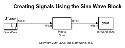
The Matrix Sum block sums the three signals point-by-point and exports the sum to the MATLAB workspace.
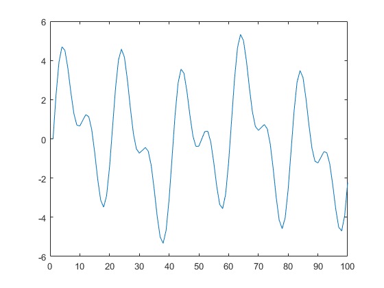
At the MATLAB command line, type plot(yout(1:100)). Your plot should look similar to this figure. This figure represents a portion of the sum of the three sinusoids. You have now added the channels of a three-channel signal and displayed the results in a figure window.
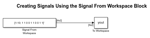
Create Signals Using Signal From Workspace Block
Frame-based processing can significantly improve the performance of your model by decreasing the amount of time it takes your simulation to run. This topic describes how to create a two-channel signal with a sample period of 1 second, a frame period of 4 seconds, and a frame size of 4 samples using the Signal From Workspace block.
Create a new Simulink model.
From the Sources library, click and drag a Signal From Workspace block into the model.
From the Simulink Sinks library, click and drag a To Workspace block into the model.
Connect the two blocks.
Double-click the Signal From Workspace block, and set the block parameters as follows:
Signal = [1:10; 1 1 0 0 1 1 0 0 1 1]'
Sample time = 1
Samples per frame = 4
Form output after final data value by =
Setting to zero
Based on these settings, the Signal From Workspace block outputs a two-channel signal with a sample period of 1 second, frame period of 4 seconds, and frame size of four samples. After the block outputs the signal, all subsequent outputs have a value of zero. The two channels contain these values:
Channel 1: 1, 2, 3, 4, 5, 6, 7, 8, 9, 10, 0, 0,...
Channel 2: 1, 1, 0, 0, 1, 1, 0, 0, 1, 1, 0, 0,...
Save these parameters and close the dialog box by clicking OK.
In the Debug tab of the model toolstrip, under Information Overlays, click Signal Dimensions.
Run the model.
This figure is a graphical representation of the model behavior during simulation. You can also open the equivalent model ex_usingsfwblkfb.
At the MATLAB command line, type yout. This is the output at the MATLAB command line. The block appends zeros at the end of each channel. You have now successfully created a two-channel signal and exported it to the MATLAB workspace.
yout =

     1     1
     2     1
     3     0
     4     0
     5     1
     6     1
     7     0
     8     0
     9     1
    10     1
     0     0
     0     0
Combine Signals Using Matrix Concatenate Block
You can combine individual signals into signals of larger dimensions using the Matrix Concatenate block. To combine signals, all signals must have the same frame rate and frame size.
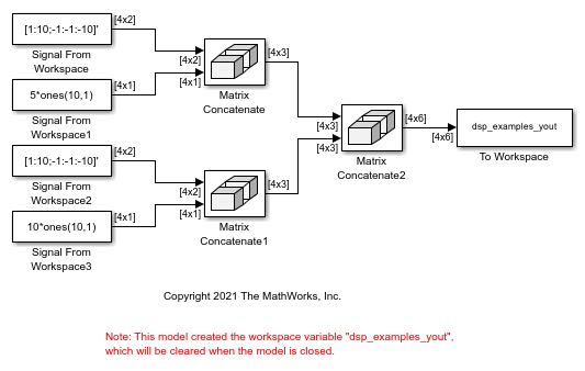
In this example, the Matrix Concatenate block combines a 4-by-2 and a 4-by-1 signal to form a 4-by-3 signal and two 4-by-3 signals to form a single 4-by-6 signal.
Open and run the ex_combiningsignals.slx model.
In all the Signal From Workspace blocks in the model, the Sample time parameter is set to 1, and the Samples per frame parameter is set to 4. The signals that the Signal From Workspace blocks output have a frame size of 4. The first two Matrix Concatenate blocks concatenate a 4-by-2 and a 4-by-1 signal in the second dimension to form a 4-by-3 signal. The third Matrix Concatenate block concatenates the two 4-by-3 signals in the second dimension and outputs a signal of size 4-by-6.
When you input the 4-by-6 signal to a block and set the Input processing parameter to Columns as channels (frame based), the block performs frame-based processing. In the frame-based processing mode, each signal column is a channel (frame), and the block processes the signal data one frame at a time.