Parametric Equalizer
Design parametric equalizer
Compatibility
Note
The Parametric Equalizer block has been removed. For new models, use the Single-Band Parametric EQ (Audio Toolbox) block.
Library
Filtering / Filter Designs
dspfdesign
Description
This block brings the filter design capabilities of the filterBuilder function to the Simulink® environment.
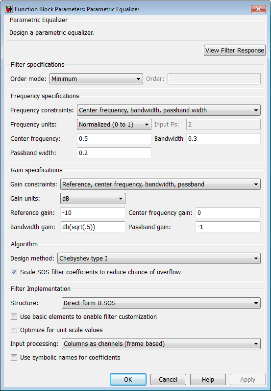
Dialog Box
The Data Types and Code Generation panes are not available for blocks in the DSP System Toolbox™ Filter Designs library.
Parameters of this block that do not change filter order or structure are tunable.
- View filter response
This button opens the Filter Visualization Tool (FVTool) from the Signal Processing Toolbox™ product. You can use the tool to display:
Magnitude response, phase response, and group delay in the frequency domain.
Impulse response and step response in the time domain.
Pole-zero information.
The tool also helps you evaluate filter performance by providing information about filter order, stability, and phase linearity. For more information on FVTool, see the Signal Processing Toolbox documentation.
Filter Specifications
- Order mode
Select
Minimumto design a minimum order filter that meets the design specifications, orSpecifyto enter a specific filter order. The order mode also affects the possible frequency constraints, which in turn limit the gain specifications. For example, if you specify aMinimumorder filter, the available frequency constraints are:Center frequency, bandwidth, passband widthCenter frequency, bandwidth, stopband width
If you select
Specify, the available frequency constraints are:Center frequency, bandwidthCenter frequency, quality factorShelf type, cutoff frequency, quality factorShelf type, cutoff frequency, shelf slope parameterLow frequency, high frequency
- Order
Specify the filter order. This parameter is enabled only if the Order mode is set to
Specify.
Frequency specifications
Depending on the filter order, the possible frequency constraints change. Once you choose the frequency constraints, the input boxes in this area change to reflect the selection.
- Frequency constraints
Select the specification to represent the frequency constraints. The following options are available:
Center frequency, bandwidth, passband width(available for minimum order only)Center frequency, bandwidth, stopband width(available for minimum order only)Center frequency, bandwidth(available for a specified order only)Center frequency, quality factor(available for a specified order only)Shelf type, cutoff frequency, quality factor(available for a specified order only)Shelf type, cutoff frequency, shelf slope parameter(available for a specified order only)Low frequency, high frequency(available for a specified order only)
- Frequency units
Select the frequency units from the available drop down list (
Normalized,Hz,kHz,MHz,GHz). IfNormalizedis selected, then the Input Fs box is disabled for input.- Input Fs
Enter the input sampling frequency. This input box is disabled for input if
Normalizedis selected in the Frequency units input box.- Center frequency
Enter the center frequency in the units specified by the value in Frequency units.
- Bandwidth
The bandwidth determines the frequency points at which the filter magnitude is attenuated by the value specified as the Bandwidth gain in the Gain specifications section. By default, the Bandwidth gain defaults to
db(sqrt(.5)), or –3 dB relative to the center frequency. The Bandwidth property only applies when the Frequency constraints are:Center frequency, bandwidth, passband width,Center frequency, bandwidth, stopband width, orCenter frequency, bandwidth.- Passband width
The passband width determines the frequency points at which the filter magnitude is attenuated by the value specified as the Passband gain in the Gain specifications section. This option is enabled only if the filter is of minimum order, and the frequency constraint selected is
Center frequency, bandwidth, passband width.- Stopband width
The stopband width determines the frequency points at which the filter magnitude is attenuated by the value specified as the Stopband gain in the Gain specifications section. This option is enabled only if the filter is of minimum order, and the frequency constraint selected is
Center frequency, bandwidth, stopband width.- Low frequency
Enter the low frequency cutoff. This option is enabled only if the filter order is user specified and the frequency constraint selected is
Low frequency, high frequency. The filter magnitude is attenuated by the amount specified in Bandwidth gain.- High frequency
Enter the high frequency cutoff. This option is enabled only if the filter order is user specified and the frequency constraint selected is
Low frequency, high frequency. The filter magnitude is attenuated by the amount specified in Bandwidth gain.
Gain Specifications
Depending on the filter order and frequency constraints, the possible gain constraints change. Also, once you choose the gain constraints the input boxes in this area change to reflect the selection.
- Gain constraints
Select the specification array to represent gain constraints, and remember that not all of these options are available for all configurations. The following is a list of all available options:
Reference, center frequency, bandwidth, passbandReference, center frequency, bandwidth, stopbandReference, center frequency, bandwidth, passband, stopbandReference, center frequency, bandwidth
- Gain units
Specify the gain units either
dBorsquared. These units are used for all gain specifications in the dialog box.- Reference gain
The reference gain determines the level to which the filter magnitude attenuates in Gain units. The reference gain is a floor gain for the filter magnitude response. For example, you may use the reference gain together with the Center frequency gain to leave certain frequencies unattenuated (reference gain of 0 dB) while boosting other frequencies.
- Bandwidth gain
Specifies the gain in Gain units at which the bandwidth is defined. This property applies only when the Frequency constraints specification contains a
bandwidthparameter, or isLow frequency, high frequency.- Center frequency gain
Specify the center frequency in Gain units
- Passband gain
The passband gain determines the level in Gain units at which the passband is defined. The passband is determined either by the Passband width value, or the Low frequency and High frequency values in the Frequency specifications section.
- Stopband gain
The stopband gain is the level in Gain units at which the stopband is defined. This property applies only when the Order mode is minimum and the Frequency constraints are
Center frequency, bandwidth, stopband width.- Boost/cut gain
The boost/cut gain applies only when the designing a shelving filter. Shelving filters include the
Shelf typeparameter in the Frequency constraints specification. The gain in the passband of the shelving filter is increased by Boost/cut gain dB from a floor gain of 0 dB.
Algorithm
- Design method
Select the design method from the drop-down list. Different methods are available depending on the chosen filter constraints.
- Scale SOS filter coefficients to reduce chance of overflow
Select the check box to scale the filter coefficients.
Filter Implementation
- Structure
Specify filter structure. Choose from:
Direct-form I SOS
Direct-form II SOS
Direct-form I transposed SOS
Direct-form II transposed SOS
- Use basic elements to enable filter customization
Select this check box to implement the filter as a subsystem of basic Simulink blocks. Clear the check box to implement the filter as a high-level subsystem. By default, this check box is cleared.
The high-level implementation provides better compatibility across various filter structures, especially filters that would contain algebraic loops when constructed using basic elements. On the other hand, using basic elements enables the following optimization parameters:
Optimize for zero gains — Terminate chains that contain Gain blocks with a gain of zero.
Optimize for unit gains — Remove Gain blocks that scale by a factor of one.
Optimize for delay chains — Substitute delay chains made up of n unit delays with a single delay by n.
Optimize for negative gains — Use subtraction in Sum blocks instead of negative gains in Gain blocks.
- Optimize for unit-scale values
Select this check box to scale unit gains between sections in SOS filters. This parameter is available only for SOS filters.
- Input processing
Specify how the block should process the input. The available options may vary depending on he settings of the Filter Structure and Use basic elements for filter customization parameters. You can set this parameter to one of the following options:
Columns as channels (frame based)— When you select this option, the block treats each column of the input as a separate channel.Elements as channels (sample based)— When you select this option, the block treats each element of the input as a separate channel.
- Rate options
When the Filter type parameter specifies a multirate filter, select the rate processing rule for the block from following options:
Enforce single-rate processing— When you select this option, the block maintains the sample rate of the input.Allow multirate processing— When you select this option, the block adjusts the rate at the output to accommodate an increased or reduced number of samples. To select this option, you must set the Input processing parameter toElements as channels (sample based).
- Use symbolic names for coefficients
Select this check box to enable the specification of coefficients using MATLAB® variables. The available coefficient names differ depending on the filter structure. Using symbolic names allows tuning of filter coefficients in generated code. By default, this check box is cleared.
Supported Data Types
| Port | Supported Data Types |
|---|---|
Input |
|
Output |
|
Version History
Introduced in R2007a