ctf2sysobj
Description
uses additional options specified in the name-value arguments. Use this syntax with any of
the input arguments in previous syntaxes.ctf = ctf2sysobj(___,Name=Value)
Examples
Design a sixth-order bandpass elliptic filter. Obtain the numerator and denominator coefficients in CTF format. The size of the filter coefficients matrices indicate three fourth-order sections.
[Num,Den] = ellip(6,3,50,[0.3 0.6],"bandpass","ctf")
Num = 3×5
0.2275 -0.0435 -0.1999 -0.0435 0.2275
0.2275 -0.1070 0.1733 -0.1070 0.2275
0.2275 -0.1188 0.2423 -0.1188 0.2275
Den = 3×5
1.0000 -0.6236 1.6521 -0.5161 0.6936
1.0000 -0.5779 1.3890 -0.5327 0.8714
1.0000 -0.5568 1.2684 -0.5468 0.9715
Convert the filter in the CTF format to a System object. The ctf2sysobj function returns a dsp.FourthOrderSectionFilter object.
ctfObj = ctf2sysobj(Num,Den)
ctfObj =
FourthOrderSectionFilter with properties:
Numerator: [3×5 double]
Denominator: [3×5 double]
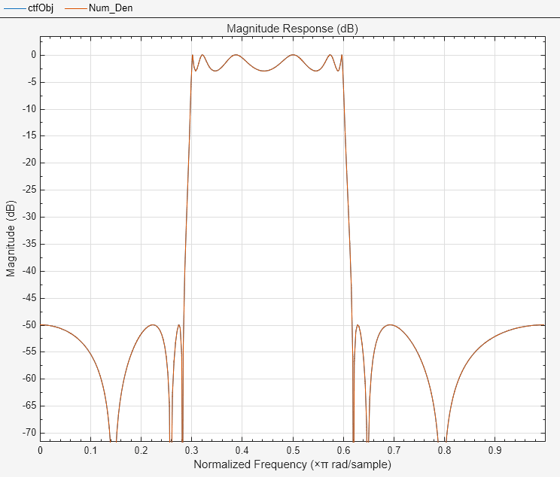
Visualize the magnitude response of the System object and of the filter representation in numerator and denominator coefficients. Both filter representations give the same magnitude response.
fa = filterAnalyzer(ctfObj); addFilters(fa,Num,Den)

Define a CTF numerator array for a cascade of two FIR filters of order 100. Convert the cascade of filters to a System object.
Num = [designLowpassFIR(FilterOrder=100); ...
designHighpassFIR(FilterOrder=100)];
Hsys = ctf2sysobj(Num)Hsys =
dsp.FilterCascade with properties:
Stage1: [1×1 dsp.FIRFilter]
Stage2: [1×1 dsp.FIRFilter]
CloneStages: true
Customize the conversion from CTF to System object and add filter cascade stages.
Design an eight-order Butterworth peak IIR filter. The number of columns in the filter coefficients, B and A, indicate that the peak filter is divided in second-order sections. The vector of scale values, g, contains the gain for the four stages and the overall system gain.
[B,A,g] = designNotchPeakIIR(FilterOrder=8, ...
QualityFactor=5,HasScaleValues=true)B = 4×3
1.0000 2.0000 1.0000
1.0000 -2.0000 1.0000
1.0000 2.0000 1.0000
1.0000 -2.0000 1.0000
A = 4×3
1.0000 0.2738 0.8880
1.0000 -0.2738 0.8880
1.0000 0.1067 0.7455
1.0000 -0.1067 0.7455
g = 5×1
0.1479
0.1479
0.1380
0.1380
1.0000
Convert the filter coefficients to a System object.
sosSys = ctf2sysobj(B,A,g)
sosSys =
dsp.SOSFilter with properties:
Structure: 'Direct form II transposed'
CoefficientSource: 'Property'
Numerator: [4×3 double]
Denominator: [4×3 double]
HasScaleValues: true
ScaleValues: [5×1 double]
Show all properties
By default, the ctf2sysobj function generates a dsp.SOSFilter System object for IIR filters of the order 2 or less. To generate a dsp.FilterCascade System object, specify the ForceCascade name-value argument as true. You can add filter stages in the next step.
Convert the filter coefficients to a dsp.FilterCascade System object.
ctfSys = ctf2sysobj(B,A,g,ForceCascade=true)
ctfSys =
dsp.FilterCascade with properties:
Stage1: [1×1 dsp.SOSFilter]
CloneStages: true
Add two stages to the dsp.FilterCascade System object. The stages comprise an allpass filter and a polyphase FIR sample-rate conversion filter. Display the System object. The resulting dsp.FilterCascade System object has three stages.
addStage(ctfSys, dsp.AllpassFilter) addStage(ctfSys, dsp.FIRRateConverter(3,2,triang(9))) ctfSys
ctfSys =
dsp.FilterCascade with properties:
Stage1: [1×1 dsp.SOSFilter]
Stage2: [1×1 dsp.AllpassFilter]
Stage3: [1×1 dsp.FIRRateConverter]
CloneStages: true
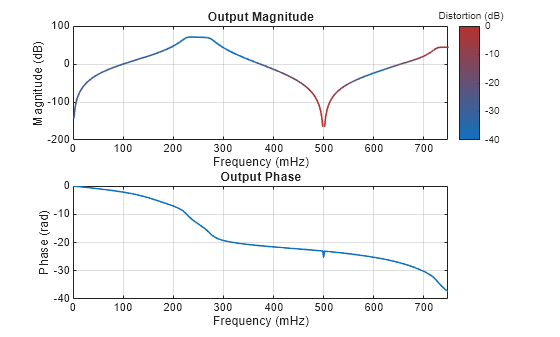
Plot the impulse response discrete-time Fourier transform (DTFT) of the three-stage dsp.FilterCascade System object.
freqzmr(ctfSys)

Input Arguments
CTF numerator coefficients, specified as a matrix, vector, or scalar.
Num must be of size
L-by-(m + 1), where:
L represents the number of filter sections.
m represents the order of the filter numerators.
For more information about the CTF format and coefficient matrices, see Specify Digital Filters in CTF Format.
Data Types: single | double
Complex Number Support: Yes
CTF denominator coefficients, specified as a matrix, vector, or scalar.
Den must be of size
L-by-(n + 1), where:
L represents the number of filter sections.
n represents the order of the filter denominators.
For more information about the CTF format and coefficient matrices, see Specify Digital Filters in CTF Format.
Note
If any element of Den(:,1) is not equal to
1, then ctf2sysobj normalizes the filter
coefficients by Den(:,1). In this case,
Den(:,1) must be nonzero.
Data Types: single | double
Complex Number Support: Yes
Scale values, specified as a real-valued scalar or as a real-valued vector with L + 1 elements, where L is the number of filter sections. The scale values represent the distribution of the filter gain across sections of the cascaded filter representation.
The ctf2sysobj function applies a gain to the filter sections
using the scaleFilterSections function depending on how you specify
g:
Scalar — The function distributes the gain uniformly across all filter sections.
Vector — The function applies the first L gain values to the corresponding filter sections and distributes the last gain value uniformly across all filter sections.
Data Types: single | double
Name-Value Arguments
Specify optional pairs of arguments as
Name1=Value1,...,NameN=ValueN, where Name is
the argument name and Value is the corresponding value.
Name-value arguments must appear after other arguments, but the order of the
pairs does not matter.
Example: ctf = ctf2sysobj([2 4 2;1 0 0],ForceCascade=true)
specifies an FIR digital filter with option to wrap each filter stage into System object.
Option to force single-stage cascades into a dsp.FilterCascade
System object, specified as one of these:
false(0) —ctf2sysobjreturns each filter stage as one of these formats:dsp.SOSFilter— Second-order sections (SOS) format.dsp.FourthOrderSectionFilter— Fourth-order sections (FOS) format.dsp.IIRFilter— Infinite impulse response (IIR) filter format.dsp.FIRFilter— Finite impulse response (FIR) filter format.
true(1) —ctf2sysobjwraps and returns each stage into adsp.FilterCascadeobject.Single-stage
dsp.FilterCascadeobject, for filters in SOS and FOS format.Multiple-stage
dsp.FilterCascadeobject, for FIR and IIR filters in CTF format.
Data Types: logical
Option to treat column vectors (Num and
Den) as row vectors (single-stage CTF), specified as on these values:
true(1) — When you specifyNumandDenas column vectors,ctf2sysobjassumes thatNumandDenlist the coefficients of a single-stage filter.false(0) — When you specifyNumandDenas column vectors,ctf2sysobjassumes that each row ofNumandDenrelates to a separate filter stage.To specify
ParseColumnVectorsAsRowsasfalse(0), you must specifyNumandDenas vectors with the same number of rows andDenmust end with nonzero elements.
Data Types: logical
Output Arguments
CTF filter System object, returned as one of these System objects:
dsp.SOSFilter— Second-order sections (SOS)dsp.FourthOrderSectionFilter— Fourth-order sections (FOS)dsp.IIRFilter— Infinite impulse response (IIR) filterdsp.FIRFilter— Finite impulse response (FIR) filterdsp.FilterCascade— Cascade ofdsp.SOSFilter,dsp.FourthOrderSectionFilter.dsp.IIRFilteranddsp.FIRFilterSystem objects
The ctf2sysobj identifies filter stages (SOS, FOS, IIR, or
FIR) from the coefficients specified in Num and
Den.
While an SOS or FOS filter stage can have multiple sections, each IIR or FIR filter stage has one section.
The order of each filter stage (stage order) is the maximum between the numerator order and denominator order.
Depending on the number of stages, maximum order of each stage, and the
value specified in ForceCascade, ctf2sysobj
returns one of the System objects in this table.
| Stage Impulse Response Type | Stage Order |
(Single-stage CTF) |
(Multiple-stage CTF) |
(Single-stage and multiple-stage CTF) |
|---|---|---|---|---|
| IIR | 1 or 2 | dsp.SOSFilter | Does not apply | Single-stage dsp.FilterCascade |
| IIR | 3 or 4 | dsp.FourthOrderSectionFilter | Does not apply | Single-stage dsp.FilterCascade |
| IIR | Greater than 4 | dsp.IIRFilter | dsp.FilterCascade | dsp.FilterCascade |
| FIR | Any | dsp.FIRFilter | dsp.FilterCascade | dsp.FilterCascade |
| Combination of the above | Does not apply | dsp.FilterCascade | dsp.FilterCascade | |
More About
Partitioning an IIR digital filter into cascaded sections improves its numerical stability and reduces its susceptibility to coefficient quantization errors. The cascaded form of a transfer function H(z) in terms of the L transfer functions H1(z), H2(z), …, HL(z) is
You can specify digital filters in the CTF format for analysis, visualization, and
signal filtering. Specify a filter by listing its coefficients B and
A in Num and Den,
respectively. You can also include the filter scaling gain across sections by specifying a
scalar or vector g.
When you specify the coefficients as L-row matrices,
it is assumed that you have specified the filter as a sequence of L cascaded transfer functions, such that the full transfer function of the filter is
where m ≥ 0 is the numerator order of the filter and n ≥ 0 is the denominator order.
If you specify both B and A as vectors, it is assumed that the underlying system is a one-section IIR filter (L = 1), with B representing the numerator of the transfer function and A representing its denominator.
If B is scalar, it is assumed that the filter is a cascade of all-pole IIR filters with each section having an overall system gain equal to B.
If A is scalar, it is assumed that the filter is a cascade of FIR filters with each section having an overall system gain equal to 1/A.
If you have an overall scaling gain or multiple scaling gains factored out from the
coefficient values, you can specify the scale values in g. Scaling
filter sections is especially important when you work with fixed-point arithmetic to
ensure that the output of each filter section has similar amplitude levels, which helps
avoid inaccuracies in the filter response due to limited numeric precision.
The gain can be a scalar overall gain or a vector of section gains.
If the gain is scalar, the value applies uniformly to all the cascade filter sections.
If the gain is a vector, it must have one more element than the number of filter sections L in the cascade. Each of the first L scale values applies to the corresponding filter section, and the last value applies uniformly to all the cascade filter sections.
If you specify the coefficient matrices and gain vector as
it is assumed that the transfer function of the filter system is
References
[1] Lyons, Richard G. Understanding Digital Signal Processing. Upper Saddle River, NJ: Prentice Hall, 2004.
Version History
Introduced in R2025a
MATLAB Command
You clicked a link that corresponds to this MATLAB command:
Run the command by entering it in the MATLAB Command Window. Web browsers do not support MATLAB commands.
Web サイトの選択
Web サイトを選択すると、翻訳されたコンテンツにアクセスし、地域のイベントやサービスを確認できます。現在の位置情報に基づき、次のサイトの選択を推奨します:
また、以下のリストから Web サイトを選択することもできます。
最適なサイトパフォーマンスの取得方法
中国のサイト (中国語または英語) を選択することで、最適なサイトパフォーマンスが得られます。その他の国の MathWorks のサイトは、お客様の地域からのアクセスが最適化されていません。
南北アメリカ
- América Latina (Español)
- Canada (English)
- United States (English)
ヨーロッパ
- Belgium (English)
- Denmark (English)
- Deutschland (Deutsch)
- España (Español)
- Finland (English)
- France (Français)
- Ireland (English)
- Italia (Italiano)
- Luxembourg (English)
- Netherlands (English)
- Norway (English)
- Österreich (Deutsch)
- Portugal (English)
- Sweden (English)
- Switzerland
- United Kingdom (English)