Blade Element Theory
R2026bBlade Element Theory block
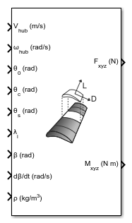
To add a block to a model, double-click the canvas and start typing the block name. Then, select the block from the list.
Libraries:
Aerospace Blockset /
Rotor Systems /
Rotor Aerodynamics
Description
The Blade Element Theory block computes aerodynamic forces and moments generated by a rotating rotor using blade element theory. The block divides each rotor blade into spanwise elements, computes local aerodynamic forces using airfoil characteristics and flow conditions, and integrates these forces along the blade span and across all blades to obtain net hub forces and moments. The block expects the input velocities and provides the output forces and moments in the hub reference frame, which is a z-upward coordinate frame.
The block supports rigid blades with flap and optional lag motion, nonuniform and dynamic inflow distributions, and optional outputs of distributed aerodynamic loads. The Blade Element Theory block can be easily integrated with Dynamic Inflow (3-State) and Dynamic Inflow (Finite-State), and with the Rigid Blade (Flap and Lag) block for comprehensive rotorcraft modeling, including preliminary design analysis, performance evaluation, and stability analysis.
Limitations
The block does not support simulation in Accelerator mode, Rapid Accelerator mode, or code generation.
Ports
Input
Output
Parameters
Algorithms
Use the Blade Element Theory block to compute the aerodynamic forces and moments generated by a rotating rotor using blade element theory. The block evaluates aerodynamic loads at discrete blade elements and integrates these loads along the blade span and across all blades.
The Blade Element Theory block computes aerodynamic forces only. Blade flap and optional lag motion are provided as inputs and are not solved internally.
Blade Element Discretization
The block divides each rotor blade into spanwise blade elements using the non‑dimensional radial locations specified by the Blade element edges parameter. These locations define the extremities of each blade element.
From these radial locations, the block computes the spanwise length and midpoint of each blade element. All aerodynamic quantities are evaluated at the blade element midpoints.
Note
The Blade Element Theory block does not separately include root cutout or tip loss factor. It is expected that the limits mentioned exclude the aerodynamically inefficient portion of the blade.
Per‑Blade and Per‑Element
For each simulation step, the block loops over:
Each blade
Each blade element along the span
At each blade element, the block evaluates local flow conditions, aerodynamic coefficients, and elemental forces.
Inflow and Local Geometry Evaluation
The block evaluates the induced inflow at each blade element using the inflow input. The inflow can be specified as:
A scalar uniform inflow
A radially varying, axisymmetric inflow
Spanwise and azimuthally varying inflow
When the Custom inflow distribution option is enabled, the block interpolates the inflow input defined at the specified radial locations through the Inflow radial distribution parameter to obtain the inflow at each blade element midpoint.
The Blade Element Theory block also evaluates the local chord and geometric twist at each blade element. When these quantities are provided as distributions, the block uses linear interpolation. For locations outside the specified range, values are held constant at the nearest boundary.
Local Geometry and Pitch
At each blade element:
Evaluate the local chord:
Use a constant value if specified as a scalar.
Use linear interpolation if specified as a matrix.
Evaluate the local geometric twist:
Linear
Ideal
Custom, using linear interpolation within the provided range and clamping outside the range.
Combine collective, cyclic, and geometric contributions to compute the local pitch angle.
Local Velocities and Aerodynamic Angles
Using hub velocities, rotor speed, induced inflow, and blade flap and lag inputs, the block computes the local relative flow velocity at each blade element. From this relative velocity and local blade pitch, the block computes the local angle of attack. Blade flap and lag inputs influence the local velocity calculation but are not solved within the block. Compute flap and lag motion by solving the rigid blade flap-lag equations, such as implemented in the Rigid Blade (Flap and Lag) block.
Compute the relative flow magnitude:
Compute the local inflow angle ϕ and angle of attack α:
Aerodynamic Forces
At each blade element, the block computes elemental lift and drag using the specified airfoil model. Lift and drag coefficients can be provided as constants or as tabulated data.
These elemental force components are computed in the blade reference frame.
If provided as constants:
If provided as matrices:
The block resolves elemental lift and drag into:
Normal force
Tangential force
Radial force
Use interpolation to evaluate coefficients at the current operating point.
Force and Moment Integration
The Blade Element Theory block integrates elemental forces along the blade span and sums contributions from all blades to compute net forces and moments at the rotor hub.
When enabled, the block also outputs the spanwise distributions of normal, tangential, and radial forces, which can be used as inputs to Dynamic Inflow (Finite-State),Dynamic Inflow (3-State) or Rigid Blade (Flap and Lag) blocks.
Note
All physical quantities in these equations are dimensional (for example, chord c, relative velocity Urel, and air density ρ).
Compute elemental lift and drag as:
Resolve elemental forces into:
The block sums elemental forces across all blade elements and blades to compute the net hub forces and moments.
Note
The Blade Element Theory block accepts input velocities and outputs forces and moments in the hub reference frame, with the Z-axis pointing upward and the X-axis pointing towards the rear of the vehicle.
For forward flight at speed V, the hub velocity input is Vhub = [-V; 0; 0].
Hub forces (Fhub = [H; Y; T]):
H — Drag force in the disk plane, positive rearward (opposing forward velocity)
Y — Side force in the disk plane, positive towards the advancing side
T — Thrust normal to the disk plane, positive upward
Hub moments (Mhub = [Mx; My; Q]):
Mx — Rolling moment, positive toward the retreating side
My — Pitching moment, positive rearward
Q — Rotor shaft torque about the shaft axis, positive when external torque is required to turn the rotor
References
[1] Leishman, Gordon J. Principles of Helicopter Aerodynamics with CD Extra. Cambridge University Press, 2006.
[2] Johnson, Wayne. Rotorcraft Aeromechanics. Vol. 36. Cambridge University Press, 2013.
Version History
Introduced in R2026b

