Troubleshoot SDFM Operation Issues
Most issues encountered when using the sigma delta filter module (SDFM) model on TI C2000 devices originate from insufficient voltage or a missing ground connection at the sigma delta modulator (SDM) LDOIN pin. Before inspecting model configuration parameters or device registers, verify that the SDM power supply is correctly applied and that the clock and data signals between the SDM and SDFM meet expected voltage and timing requirements. Validating these hardware conditions first helps isolate root causes early and avoids unnecessary software-level debugging.
SDFM Output Is Zero or Invalid
Possible Causes
Incorrect hardware connections between DAC, SDM, ePWM, and SDFM
Insufficient voltage at the SDM LDOIN pin
Invalid DAC input waveform
Missing or invalid SDM clock
Weak or invalid SDM DOUT signal
Incorrect SDFM register configuration
Possible Solution
Run the SDFM example model (c28x7x_sdfm.slx) in Monitor & Tune
mode. Confirm that the SDFM output reflects the expected analog input waveform. If the
output is zero or distorted, proceed with the checks below. For more information, see
Using Sigma Delta Filter Module (SDFM) to Measure the Analog Input Signal.
No Signal Reaches SDFM Input
Possible Causes
Loose or incorrect jumper connections
Missing clock or data routing
Possible Solution
Verify the following hardware connections:
DAC output connects to the SDM analog input
SDM digital output connects to the SDFM data input
ePWM output connects to both the SDM clock input and the SDFM clock input
Inspect all jumpers for correct placement and continuity. Measure the 3.3 V rail using a multimeter to confirm stable voltage.
SDM Digital Output Signal Is Too Weak
Possible Causes
Insufficient voltage at the SDM LDOIN pin
Missing ground reference on AGND
Possible Solution
Check the SDM power configuration:
If the jumper is set to Ext, confirm that J5 supplies at least 3.3–4 V to LDOIN and that AGND is connected.
If the jumper is set to Iso, remove the VDD1 connection and retain the AGND connection.
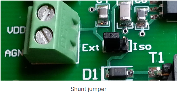
Use Iso mode when possible. Ensure that AGND is
always connected to ground. Without a valid ground reference, the SDM digital output does
not reach valid logic levels.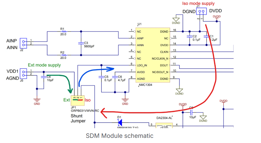
DAC Output Does Not Match Expected Waveform
Possible Causes
Incorrect DAC configuration
Invalid input stimulus
Possible Solution
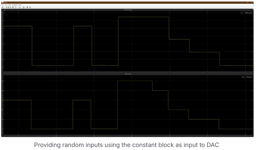
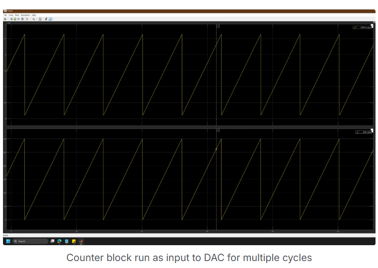
Create a minimal model that includes only the DAC and an ADC block. Drive the DAC using a Constant or Counter block. Use External Mode to confirm that the ADC captures the expected waveform. If available, use an oscilloscope to verify that the DAC output varies from 0 to 3.3 V as the digital input changes.
SDM Clock Signal Is Invalid or Unstable
Possible Causes
Incorrect ePWM frequency or duty cycle
Measurement limitations
Possible Solution
Probe the ePWM output using an oscilloscope. Confirm that the signal:
Has approximately 50% duty cycle
Operates within the supported SDM clock frequency range (for example, 5–10 MHz)
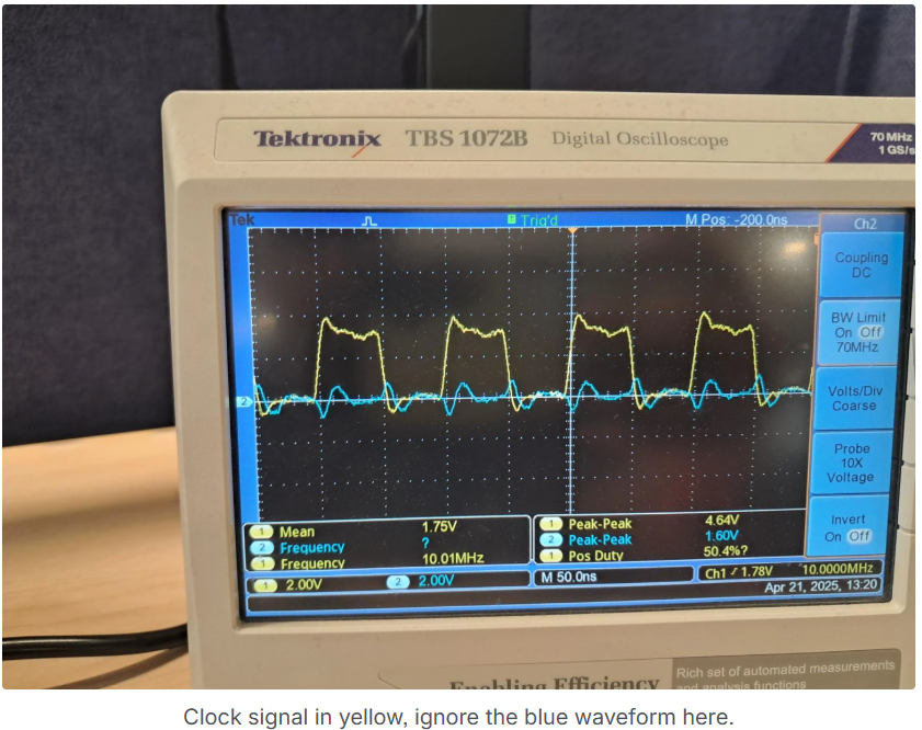
Avoid very high frequencies unless verified with appropriate oscilloscope bandwidth.
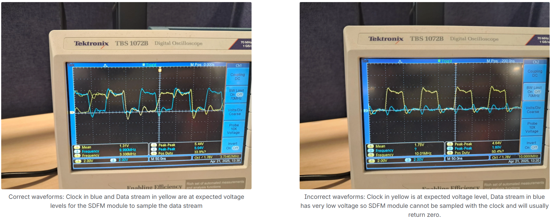
SDM DOUT Signal Is Not Detected by SDFM
Possible Causes
Insufficient SDM supply voltage
Poor signal integrity
Possible Solution
Probe the SDM DOUT pin and the SDM clock pin simultaneously. Confirm that:
The DOUT voltage level is close to the clock voltage level
The signal transitions cleanly between logic levels
If the DOUT signal is flat or significantly lower than the clock level, recheck the SDM power configuration and grounding.
Note
Limited oscilloscope bandwidth can distort the appearance of the DOUT and CLK waveforms, but the observed transitions are adequate for debugging.
SDFM Configuration Does Not Match Model Settings
Possible Causes
Incorrect GPIO assignment
Block parameters not applied correctly to hardware registers
Possible Solution
Confirm that the model uses the correct SDFM instance and GPIO pins. Build and deploy the model to generate an executable. Load the executable in Code Composer Studio™ and inspect SDFM registers related to:
Filter configuration
Data format
Threshold and comparator settings
Compare register values against the device Technical Reference Manual.
Issue Persists After Configuration Verification
Possible Causes
Hardware fault in SDFM or controlCARD
Possible Solution
Test an alternate SDFM channel. If available, deploy the model to a different controlCARD to rule out board-specific issues.
Intermittent or Noisy SDFM Output
Possible Causes
Signal integrity issues
Grounding or voltage rail instability
Possible Solution
Use an oscilloscope to verify SDM clock and data signals. Confirm clean edges, consistent timing, and valid voltage levels. Measure all voltage rails and ground continuity with a multimeter.
See Also
Using Sigma Delta Filter Module (SDFM) to Measure the Analog Input Signal | C28x/C29x SDFM | SDFM