このページは機械翻訳を使用して翻訳されました。元の英語を参照するには、ここをクリックします。
F28P65x メモリ構成
F28P65x デバイスのメモリ構成は、以前のデバイスとは若干異なります。F28P65x デバイスには、CPU1 または CPU2 に割り当てることができる 5 つのフラッシュ バンクがあります。さらに、CPU1 または CLA は LS RAM を使用できますが、RAM Dx メモリは CPU1 または CPU2 のいずれかにマップできます。
フラッシュ バンク構成
C2000™マイクロコントローラーブロックセット では、フラッシュ バンク 0 ~ 2 が CPU1 に割り当てられ、フラッシュ バンク 3 と 4 が CPU2 に割り当てられます。
CCS ツールでバンクを同様に構成しないと、Simulink® で生成された .out ファイルを CCS ツールの外部でダウンロードするときに、次のエラーが発生する可能性があります。Simulink のコードをダウンロードするときには、このエラーは表示されません。
C28xx_CPU2: Flash Programmer: Error erasing Bank 0 FMSTAT (STATCMD on some devices) value = 65. Operation Cancelled (0).
C28xx_CPU2: File Loader: Memory write failed: Unknown error
C28xx_CPU2: GEL: File: <generated .out file>: Load failed.
CCSツールでのフラッシュ バンクの設定
CCS ツールでフラッシュ バンクを構成するには、次の手順に従います。
F28P65x デバイスの ccxml ファイルを右クリックし、選択した構成の起動 を選択してデバッグ ビューを開きます。
デバッグ ビューで、コア C28xx_CPU1 を選択し、 [ツール] > [オンチップ フラッシュ] に移動して、CPU1 フラッシュ プラグイン GUI を開きます。
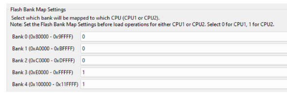
CPU1 フラッシュ プラグイン GUI の Flash Bank Map Settings の下で、画像に示すように Bank 0, 1, and 2 を CPU1 に、Bank 3 and 4 を CPU2 にマップします。

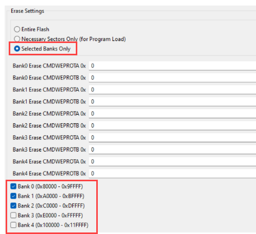
GUI の Erase Settings セクションに移動し、画像に示すように、CPU1 フラッシュ プラグインが消去できるバンクとしてフラッシュ バンク 0、1、および 2 を有効にします。

CPU1 flash プラグイン GUI の上部に移動し、Configure Clock ボタンを使用して PLL を設定します。CPU2 フラッシュへの実行可能ファイルのロードなど、CPU2 フラッシュ プラグイン操作を実行する前に、必ずこの手順を完了してください。
40次に、デバッグ ビューでコア C28xx_CPU2 を選択し、メニュー オプション Tools > On_Chip Flash に移動します。このアクション、CPU2 フラッシュ プラグイン GUI が開きます。
手順 3 および 4 と同様に、CPU2 フラッシュ プラグイン GUI で、バンク 0 ~ 2 を CPU1 にマップし、バンク 3 および 4 を CPU2 にマップします。さらに、Erase settings の下で、バンク 3 とバンク 4 を有効にして、CPU2 のフラッシュ プラグインによって消去できるようにします。
CCS がフラッシュ プラグイン GUI で構成した設定を記憶していることを確認するには、GUI の下部にある Remember My Settings ボタンをクリックします。このアクションにより、将来の反復のために設定が保存されます。
RAM D メモリ構成
C2000 Microcontroller Blockset の F28P65x デバイス用に出荷された .cmd ファイルは、RAM D メモリを次のように分割します。RAMD0 と RAMD1 は CPU1 に割り当てられ、RAMD2 から RAMD5 は CPU2 に割り当てられます。
LS RAM構成
LS RAM メモリは、CPU1 と CLA によって排他的にアクセスできます。このメモリ割り当ては、モデル構成パラメーターで構成できます。Hardware Implementation > Target hardware resources > Build オプションに移動して、Configure CLA program and data memory を選択します。