PX4 PWM Output
Configure PWM outputs for servo motors and ESC control
PX4 PWM Output will be removed in a future release. For more information, see Version History.
Add-On Required: This feature requires the UAV Toolbox Support Package for PX4 Autopilots add-on.

Libraries:
UAV Toolbox Support Package for PX4 Autopilots /
PX4 Utility Blocks
Description
The PX4 PWM Output block helps you to configure the PWM output from the PX4® flight controller board. The block accepts time value (in microseconds) that represents the ON period of PWM signal for a particular channel, and passes the same to the corresponding PWM channels on the board.
The PX4 PWM Output block also accepts signals for arming the flight controller.
During Connected IO simulation, this block writes data to the peripherals of the hardware.
Configure Actuators
For Firmware version 1.14, the PWM & AUX pins need to be configured in QGroundControl before the PWM Output block can be used in Simulink. To do this, QGroundControl version 4.2.3 is needed which can be downloaded from this location.
Note
Configuring the actuators is not required for Hardware-in-the-loop or PX4 Host Target simulations.
To configure the actuators, perform these steps.
Perform the Hardware setup process for your Autopilot.
Launch QGroundControl 4.2.8 (QGC) and allow it connect to your Autopilot.
Once QGC is connected, go to Vehicle Setup -> Actuators tab.

Assign the following sequence of Motors against each Main Channel.

It is recommended to change the Minimum PWM value of each channel to 1000 and Maximum PWM value to 2000.
Assign the following sequence of Motors against each AUX Channel.

Examples
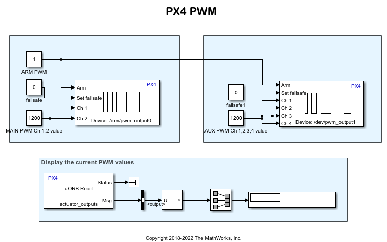
Getting Started with PWM Blocks for PX4 Autopilots
Use the PX4 PWM Output block to generate signals on the PWM pins of a Pixhawk Series controller, and verify the PWM values.
Ports
Input
Parameters
Main tab
Select the category (Main or AUX) to identify and select the corresponding channels. After you select this category, you can select the channels in the parameter list, for Main and AUX, separately.
Select the channels to which you want to send the values for PWM ON time (the
channels to which you connect servo motors or ESC). The Ch inputs to
the block appear based on the selection in this parameter list.
Note
Ensure that you select all the channels that belong to the same channel group. If you need to connect to PWM channels that are in different groups, select all channels in all the desired groups. Only one PX4 PWM Output block per channel category (Main or AUX) is allowed in the entire Simulink model.
Tip
To identify the channel groups in the Pixhawk Series flight controller board, use QGroundControl application on your host computer:
Open QGroundControl.
Connect the Pixhawk Series flight controller board to the USB port of the host computer.
In QGroundControl, go to Mavlink Console, and do the following:
To identify the Main channels and their groups, enter the command
pwm info.To identify the Aux channels and their groups, enter the command
pwm info -d /dev/pwm_output1
