Model State Transition Tables by Using State Transition Table Blocks
You can use finite state machines to describe the control logic in a Simulink® model by using State Transition Table blocks. For more information about finite state machines, see Design Finite State Machines in Stateflow.
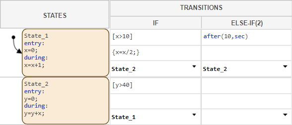
State transition tables consist of a state column that defines the operating modes of the system, and a transition column that defines when and how the states activate and deactivate. Additionally, state transition tables can input and output data to the Simulink model, and store data locally. This image shows an example of a State Transition Table block with two states and transition actions.
Create States and State Actions
States define what the operating modes are and what actions the system takes when the operating mode is active. You can add and delete states or use state actions to specify what actions occur when the state is active or when the table enters or exits the state. You can also specify a state as the default state, which is the state that activates when the chart or parent state activates.
Add or Delete State
To add a state, point to a state in the table. At the bottom of the state, the Add state below button appears. Click the button.
To edit the text inside a state, click the state. A cursor appears.
Note
State names cannot contain spaces or begin with a number. Each state name must be unique.
To add a child state, point to the state and click Add child state. To convert a state into a child state, right-click the state and select Make child. For more information about parent and child states, see Create Parent and Child Operating Modes in State Transition Tables.
To delete a state, right-click the state and select Delete state.
Add State Actions
To add state actions, click the state to edit the text of the state.. Then, create a new line below the state name by pressing Enter.
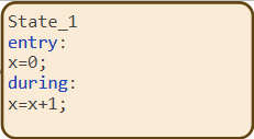
For example, this state is named State_1. When the table
enters the state, it sets x to 0. Then, it
increments x every time step the state is active. For more
information about state actions, see Add Executable Code.
Select Initial Active State
The default transition ![]() identifies which state first becomes active when the table
or parent state initializes.
identifies which state first becomes active when the table
or parent state initializes.
To move the default transition, right-click a state and select Set to default.
Specify Transitions Between States
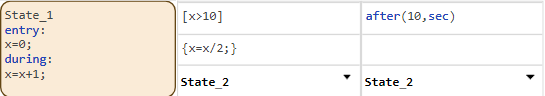
The transition columns specify when the system moves from one operating mode to
another and any actions the table takes when this occurs. For example, in this
image, State_1 has two defined transitions.
Set Condition, Action, and Destination
Each transition has three optional rows that define how it operates.
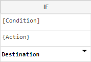
The first row is a condition that must be met before the table transitions from this state to the destination state. The second row is an action that executes when the table transitions from this state to the destination state. The third row is the destination state that the table transitions to when the condition row is valid.
For information about transitions and their limitations, see Move Between States.
Add or Delete Transition Column
If your table requires more than two transitions, you can add transition columns in these ways:
To append a transition column to the end of the table, right-click the table and select Append transition column.
To insert a transition column between two existing transition columns, right-click the left column and select Insert transition column.
To delete a transition column, right-click the column and select Delete transition column.
Specify Time Delays for Transitions
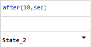
To execute a transition after a specified period of time, you can use a temporal operator in a condition.
To use a temporal operator in a condition, enter the operator without
brackets. For example, to execute a transition after the state has been active
for 10 seconds, enter after(10,sec).
You can combine temporal operators with conditions. For example, the condition
after(10,sec)[a>6] is valid if the state has been active
for at least 10 seconds and a is greater than
6.
For more information on temporal operators, see Control Chart Execution by Using Temporal Logic.
Create Data and Share with Simulink Model
State transition tables use variables called data or symbols. You can create data by entering variables in state actions or transitions, or by creating them in the Symbols pane. When you create variables in state actions, you must define the data type in the Symbols pane before simulating the model.
To learn how to add data with the Symbols pane, see Add Data by Using the Symbols Pane.
When you create an input or output data, event, or message, the Simulink model adds an input or output port to the State Transition Table block. You can also create input or output ports by dragging a signal line to the State Transition Table block.