Main Content

Quadrature Shaft Decoder

Decode incremental shaft encoder output

Since R2019b

  • Quadrature Shaft Decoder block

Libraries:
Simscape / Electrical / Control / Observers

Description

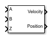
The Quadrature Shaft Decoder block measures the shaft rotation from an encoder block, such as the Incremental Shaft Encoder, and outputs the velocity and position.

The block counts the transitions of a pair of digital signals, A and B, that are positioned 90° out of phase. The block determines the direction and relative position by counting only one of the two signals changes per tick. The angular velocity is obtained by measuring the frequency of either signal.

Ports

Input

expand all

Simulink digital signal A, specified as a scalar, which is 90° out-of-phase with digital signal B.

Data Types: single | double

Simulink digital signal B, specified as a scalar, which is 90° out-of-phase with digital signal A.

Data Types: single | double

Simulink signal, specified as a scalar, associated with the decoder index pulse that is used to reset the position calculation.

Data Types: single | double

Output

expand all

Simulink signal, specified as a scalar, associated with the shaft rotational velocity.

Data Types: single | double

Simulink signal, specified as a scalar, associated with the shaft angle of rotation.

Data Types: single | double

Parameters

expand all

Number of pulses per revolution of the encoder shaft.

Time between consecutive block executions, in s. During execution, the block produces outputs and, if appropriate, updates its internal state. For more information, see What Is Sample Time? and Specify Sample Time.

If this block is inside a triggered subsystem, you can set this block to inherit the sample time by setting this parameter to -1. If this block is in a continuous variable-step model, specify the sample time explicitly by using a positive scalar.

Extended Capabilities

C/C++ Code Generation
Generate C and C++ code using Simulink® Coder™.

Version History

Introduced in R2019b