Spline
3 次内挿による平面曲線または空間曲線

ライブラリ:
Simscape /
Multibody /
Curves and Surfaces
説明
この Spline ブロックは、指定された点間の 3 次内挿に基づく連続スプライン曲線を作成します。曲線は 2 次元 (平面カム プロファイルなど) または 3 次元 (ローラー コースター トラックなど) のいずれかになります。スプラインの次元は座標行列の次元に依存します。N-by-2 の行列は xy 平面の 2 次元曲線を指定します。N-by-3 の行列は 3 次元曲線を指定します。座標はすべてブロックのローカル基準フレームで分解されます。さらに、指定された端点条件に従って、開いた曲線か閉じた曲線のいずれかになります。

例
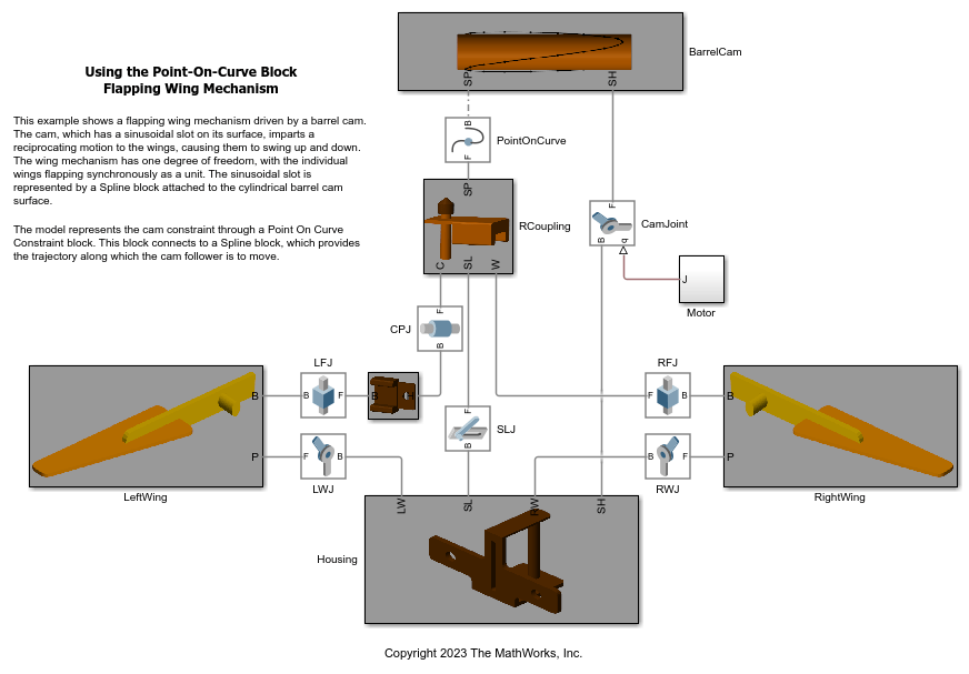
Point-On-Curve ブロックの使用:羽ばたく翼の機構
このモデルでは、筒型カムをベースにした羽ばたく翼の機構のシミュレーションを実行します。これは 1 自由度機構で、2 つの翼は互いに対して同期して羽ばたきます。Spline ブロックと Point On Curve ブロックを使用して筒型カム機構をモデル化し、翼の羽ばたく運動を作動させています。
端子
フレーム
ジオメトリ
パラメーター
拡張機能
バージョン履歴
R2015b で導入