Camshaft
This example shows how to model a camshaft using Cam and Follower (AB-PB) blocks. The camshaft has four cams, each driving a knife-edge follower on a spring. This example describes how to set up the cam profile, offset angles between the cams, and initial conditions.
Open the model to explore its blocks.
open_system('Camshaft');

Define the Cam Profile
As the cam rotates, it has a constant radius of 0.15 m between -30 to 30 degrees. From 30 to 180 degrees, the radius increases parabolically from 0.15 m to 0.35 m, and from 180 to 330 degrees, the radius decreases parabolically back to 0.15 m. Below is a plot of the cam radius in polar coordinates.
[theta_TLU, radius_TLU, length_TLU] = CamshaftGenerateCamProfile(radius_min, radius_max, theta_constant, eccentricity);
CamshaftPlotCamProfile;

The Eccentricity parameter is the perpendicular offset between the cam axle and the follower's line of action. Eccentricity changes the contact geometry and normal force direction for a given cam angle. Positive eccentricity shifts the follower's line of action in the same direction that the cam surface moves at the contact point during positive angular velocity. Positive eccentricity reduces the pressure angle during rise and increases it during fall. Rise is a period when the follower moves away from the axle, and fall is a period when the follower moves toward the axle. In this example, the cam followers have an eccentricity of 0.05 m.
Configure the Cam Offset Angles
The cams are rigidly attached to the shaft at various angles, as shown in the physical view image in the model. This physical view corresponds to the system initial state. The angles are (units of degrees):
CamFollower = ["1";"2";"3";"4"];
InitialAngle = [120;0;180;60];
Table = table(CamFollower,InitialAngle);
disp(Table);
    CamFollower    InitialAngle
    ___________    ____________

        "1"            120
        "2"              0
        "3"            180
        "4"             60
A Rotational Initial Relative Angle (AB) block sets the initial angle of Cam-Follower1 relative to the Rotational World (AB) block. Rotational Spacer (AB) blocks between the Cam-Followers define the constant angular separation between adjacent cams.
Simulate the model to observe the cam angles.
open_system('Camshaft/Cam Angle (deg)');
sim('Camshaft');
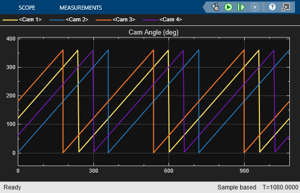
During the simulation, the cams complete three revolutions. The Rotational Motion Sensors wrap the angle between 0 and 360 degrees, making it easier to visualize each revolution in the scope. The scope results verify the initial angles of each cam.
Set Boundary Conditions and Variable Initial Targets
Each spring's B node is connected to a Translational World (PB) block, resulting in stationary nodes that have positions of 0 m. Each Cam-Follower's Ft node is connected to the Translational Spacer (PB) block, which specifies a stationary position of 0.5 m.
The model includes these high-priority initial targets:
Translational Spacer (PB) Length of 0.5 m between the Translational World (PB) and shaft axis.
Translational springs with Rest length of 0.4 m, ensuring that the springs remain compressed as the lengths of the Cam-Followers vary from about 0.15 to 0.35 m within the 0.5 m gap between the Translational World (PB) and shaft axis.
An Initial Relative Angle (AB) block with a Relative angle of 120 deg.
Rotational Spacers specifying the angles of the other three cams.
A Rotational Velocity Source (AB) drives the cam at a constant velocity of 1 degree per second.
View the Follower Responses
Simulate the model to view the knife-edge follower positions.
close_system('Camshaft/Cam Angle (deg)');
open_system('Camshaft/Cam Follower Position (m)');
sim('Camshaft');
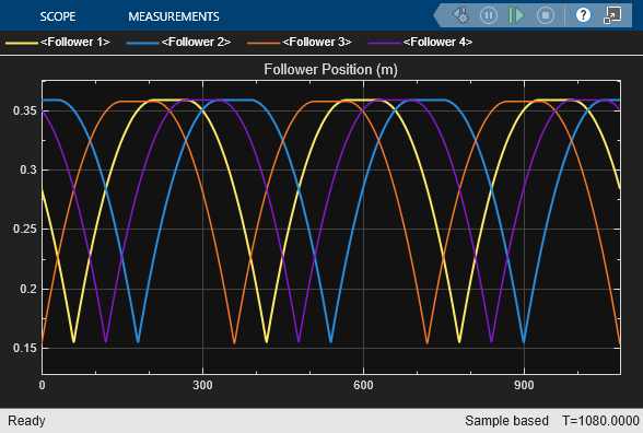
As expected from the cam profile, the cam followers undergo a parabolic rise phase, a dwell phase, and a parabolic fall phase, with positions ranging from 0.155 to 0.36 m. These positions correspond to the 0.5 m axle position minus the maximum and minimum lengths of the cam follower. The maximum and minimum lengths of the cam follower are slightly less than the 0.35 m and 0.15 m cam radii, respectively, due to the 0.05 m eccentricity.
Simulate the model to view the force of the cam on the knife-edge follower.
close_system('Camshaft/Cam Follower Position (m)');
open_system('Camshaft/Force of Cam on Cam Follower (N)');
sim('Camshaft');
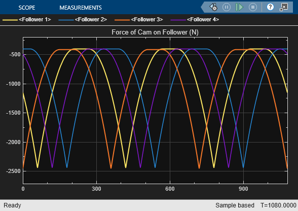
As expected due to the preload in the Translational Springs, the force exerted by the cam on the follower is always negative. This negative value indicates that the cam pushes the cam follower in the negative translational direction, which is downward in this schematic. The maximum force occurs when the cam's largest radius drives the cam follower, pushing the follower to its lowest position and compressing the spring to its shortest length. Conversely, the minimum force occurs when the cam has its smallest radius driving the cam follower.