Power Ports and Signal Power Measurement in RF Blockset
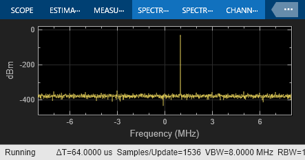
This example shows how to use power ports and measure the signal power using the spectrum analyzer.
Power Model
model = 'simrfV2_powerportdefinition_1.slx';
open(model)
sim(model)


In this model, the Simulink® signal is interpreted as a |Vrms^2 signal| referred to 1 Ohm. This is the implicit convention used in the DSP System Toolbox™.
When measuring the signal power with the spectrum analyzer, refer the measurement to 1 Ohm. Use the power option for the ports at the input and output of the system. Notice that the ports automatically add source and load impedances, and scale the signal to refer it to the specified impedance. In this way, the available power of the input signal is referred to 50 Ohm. The RF Blockset™ amplifier is thus processing a signal with the same power as the Simulink signal.
When probing internal nodes, use the voltage option in the "sensing" port to avoid mismatch in the circuit. Also, adjust the reference impedance in the spectrum analyzer to 50 Ohm.
Voltage Model
model2 = 'simrfV2_powerportdefinition_2.slx';
open(model2)
sim(model2)


In this model, the Simulink signal is interpreted as a Voltage signal. When measuring the signal power with the spectrum analyzer, refer the measurement to 50 Ohm. Notice that the two sources and the "Real-Imag to Complex" of the Power Model are replaced using a single Sine Wave block with property Output complexity set to "Complex".
In RF Blockset, use the voltage option for the ports at the input and output of the system. Add source and load impedances to avoid mismatch in the amplifier. Also add a factor of 2 to make sure that the voltage at the input of the RF Blockset amplifier has the same value as the Simulink signal. The factor of 2 takes into account the voltage division between the source and input impedances.
See Also
Amplifier | Inport | Spectrum Analyzer
