Inport
Convert Simulink input signal to RF Blockset signal

Libraries:
RF Blockset /
Circuit Envelope /
Utilities
Description
The Inport block imports Simulink® signals into the RF Blockset™ circuit envelope simulation environment. For an introduction to RF simulation, see the example, Simulate High Frequency Components. You can also modulate an input signal onto a square carrier wave in the RF Blockset circuit envelope simulation environment.
Complex-valued input signals Ik(t) + j · Qk(t) are the modulations at the frequencies {fk} specified in the Carrier frequencies parameter of the block. The input port converts the complex-valued input signals into an RF signal suitable for multicarrier simulation:
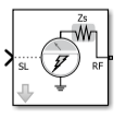
The Source type parameter specifies the Simulink signal as either current, or voltage, or power source. For more information, see How to Use Inport Block. Inport block mask icons are dynamic and show the current type of source. This table shows you how the icons on this block vary based on the type of source you set on the Source type parameter on the block.
Source type: Ideal voltage | Source type: Ideal current | Source type: Power |
|---|---|---|
|
|
|
|


Examples

Attenuate Signal Power
Use the Attenuator block to attenuate a constant signal of 20 dB by 3 dB.

Modulate Input Signal onto Square Carrier Wave
Use the Inport block to modulate input signal onto square carrier wave.
Parameters
Inport block interpretation of a Simulink signal, specified as:
Ideal voltage— The block outputs Simulink signals as voltage signals v(t) in the RF Blockset environment. When you choose an ideal voltage input port you need to manually add a series of source impedance to match the blocks connected to the input port. The following figure illustrates the internal configuration of the block.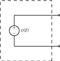
Ideal current— The block outputs Simulink signals as current signals i(t) in the RF Blockset environment. When you use an ideal current input port, you manually add a parallel source impedance to match the blocks connected to the input port. The following figure illustrates the internal configuration of the block.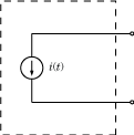
Power— The block interprets the Simulink signals, Pv(t), as available power and internally uses a voltage source, and series impedance. You use this option to import a 50 ohm environment or different reference impedance signals created using Communications Toolbox™. When you select this option, the input port automatically inserts a source impedance in your circuit as shown in the following figure.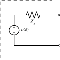
The voltage v(t) is a scaling of the Simulink signal vSL(t):
In the preceding equation, Zs is the value of the Source impedance (Ohm) parameter.
The generator delivers real power to the load Zl:
When Zl = Zs*, this generator delivers the available power |vSL(t)|2.
Source impedance for available power match, specified as a vector of positive integers in ohms
Dependencies
To enable this parameter, select Power in Source
type.
Carrier frequencies, specified as a vector or scalar in Hz, kHz, MHz, or GHz. Specify
Carrier frequencies as a positive scalar greater
than 0 when you select the Use
Square Wave parameter. In carrier frequencies, the
elements are a combination of fundamental tones and corresponding harmonics
in the Configuration block.
Select this parameter to modulate your input signal onto a square carrier wave.
Since R2026a
Select this parameter to simulate thermal noise emanating from the source impedance. The block icon updates to reflect this change.
Dependencies
To enable this parameter, set Source
type to Power .
Plot the simulation frequencies of the square carrier wave and the approximate square wave with RSM error.
Dependencies
To enable this parameter, select Use Square Wave.
Number of Fourier coefficients required to modulate an input signal onto a
square carrier wave, specified as an integer greater than or equal to
1.
Dependencies
To enable this parameter, select Use Square Wave.
Duty cycle of a square carrier wave, specified as a positive integer
between 0 and 100 in %.
Dependencies
To enable this parameter, select Use Square Wave.
Select this parameter to ground and hide the negative terminals. Clear the parameter to expose the negative terminals. By exposing these terminals, you can connect them to other parts of your model.
More About
Using the Inport block you can specify the complex envelopes of your input signals and import them as RF signals for multi-carrier simulation.
The Configuration block automatically determines the fundamental tones specified in the input ports and proposes a suitable harmonic order to capture the non-linearity of the system. You can also manually specify the harmonic order for each fundamental tone in the simulation.
In the input port, you can specify as many carrier frequencies as you want. It is recommended that you trade off the simulation bandwidth (inversely proportional to the simulation time step) and the total number of simulation frequencies.

Algorithms
The Inport block allows you to specify the complex envelopes of your input signals and import them as RF signals for multi-carrier simulation.
The power option automatically insert a source or load impedance in your network, and normalizes the signal power with respect to the specified impedance. You do not need to manually insert source and load terminations, and your signals are automatically scaled between RF Blockset and the Simulink environment that assumes an implicit 1 ohm reference impedance.

When using voltage sources and sensors, manually add source and load terminations, otherwise there might be an undesired impedance mismatch in your network. When you measure the power of a voltage signal, make sure that you use a 50Ohm reference impedance.
If you use an ideal voltage source and add a source impedance, in perfectly matched conditions, the actual voltage applied to the first block of the RF chain is half of the value of the input Simulink signal. The source impedance and the input impedance of the first block of the RF chain form a voltage divider network.

Input signal is a digital communication complex equivalent baseband signal
(I,Q). You assume an implicit carrier for the system that is equal to the
carrier frequency, Fc. You want to
model RF effects such as amplifier nonlinearity and S-parameter filters using
RF Blockset:
Enter
Fcin the Carrier Frequencies parameter.The simulation step size in the configuration block is the same as the sample time of the Simulink input signal, and it is not related to the carrier frequency.
If the RF chain does not include any modulator or demodulator, use an Outport block at the end of the chain. You can use the
Outportblock to probe the complex equivalent signal centered onFc.

Input signal is a digital communication complex input baseband signal (I,Q).
You assume that no carrier is associated with the input signal. You want to
upconvert the signal to Fc and model
RF effects such as amplifier nonlinearity and S-parameter filters:
Use to two Inport blocks for the I and Q components of the input signal. Set the Carrier Frequencies parameter of each Inport block to
0To upconvert the signal, use an IQ Modulator block. Set the Local oscillator frequency to
Fc.The simulation step size in the configuration block is the same as the sample time of the Simulink input signal, and it is not related to the Local Oscillator frequency.
Use an Outport block at the end of the chain. and probe the signal at
Fc.

Input signal is a digital communication complex equivalent baseband signal (I,Q). You want to first upconvert the signal to intermediate frequency (IF), then to RF, and model RF imperfections:

Input signal is a digital or analog real passband signal that is explicitly modulated to high frequency in Simulink domain:
Set the Carrier Frequencies parameter of each Inport block to
0and simulate RF effects.The simulation step size in the configuration block is the same as the sample time of the Simulink input signal, and it is proportional to the RF frequency.
However there is no speed benefit in using RF Blockset for real-passband simulation. This option is not recommended
