Task Preemption in a Multitasking Processor
This example shows how to force service completion in an Entity Server block using functionality available on the block Preemption tab.
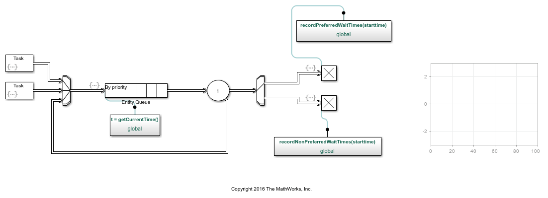
Example Model for Task Preemption
The example shows preemption(replacement) of low priority tasks by a high priority task in a multitasking processor. In the model, the Entity Server block represents the task processor presented with a capacity to process multiple concurrent tasks.
Model Behavior and Results
The following graphic shows how the model generates both low and high priority tasks.
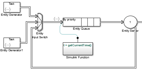
The top and bottom Entity Generator randomly generate entities that represent high and low priority tasks, respectively. Both blocks use the
exprndfunction to generate random entities. The top block usesexprnd(3), the bottom usesexprnd(1), which requires the Statistics and Machine Learning Toolbox™ license.The Entity Input Switch block merges the paths of the new low priority tasks with previously preempted tasks that are returning from the task processor (server).
The Simulink Function block runs the
getCurrentTimefunction to start a timer on the low priority tasks. When preemption occurs, a downstream Simulink Function block determines the remaining service time of the preempted tasks.The Entity Output Switch block merges the paths of the high and low priority tasks. Tasks on the merged path proceed for processing.
An Entity Server block represents a multitasking processor with capacity for multiple tasks.
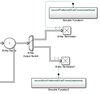
When preemption occurs, causing the Entity Server block to complete
immediately service of all low priority tasks, one of the two Simulink
Function blocks calculates the elapsed time of each departing task using
the recordPreferredWaitTimes and
recordNonPreferredWaitTimes functions. The two Entity
Terminator blocks calls these Simulink Function to
calculate the elapsed times.
If the elapsed time of a departing task is less than the service time of the
Entity Server block, meaning that preemption forced the task to
depart the server early, the Output Switch block feeds the task back
to reenter the server. If the elapsed time in the Simulink Function
getCurrentTime block is equal to the service
time of the Entity Server block, the server has completed the full
service time on the task. The entity terminates in the Entity
Terminator block.
The Dashboard Scope block shows the simulation results.
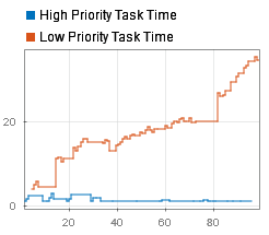
The plot displays wait time for high an low priority tasks. It can be observed that wait time of high priority tasks is significantly decreased.