Post-Layout to Pre-Layout Extraction
You can create topologies from the extracted PCB data for the extended that can be simulated (assigned to an STNET or user Transfer Net). You can access this topologies from the Pre-Layout Analysis tab of the Serial Link Designer or Parallel Link Designer app. These topologies can be used to quickly analyze network routing and resolve waveform quality and/or timing issues identified by post-layout verification.
To create topologies, select the extended nets that you want to create pre-layout schematic topologies for and click the Create Topologies button in the Post-Layout Operations area in the Post-Layout Verification tab.
Usually only uncoupled net segments is used for creating topologies. You can select Use Coupled Models option to create differential net topologies with coupled net segments. For complicated topologies this simplifies the resulting topology.
To view topologies, in the Pre-Layout Analysis tab, select the transfer net for the topology to be viewed or analyzed. Select the topology from the Topology drop-down list in the Sheet Simulation Control Panel.
The pre-layout sheet with the topology from post-layout can be simulated in pre-layout The schematic can be modified and elements can be parameterized as any pre-layout schematic. Changes to the topology in the schematic does not change the post-layout topology used in post-layout simulations.
Transmission Line Models in Topologies
For stripline models with different dielectric constants on each layer a composite dielectric is derived.
For example, the left hand cross-section is a cross-section from the stackup, where each layer can have a different dielectric constant. On the right is the model that can be represented in the transmission line editor.
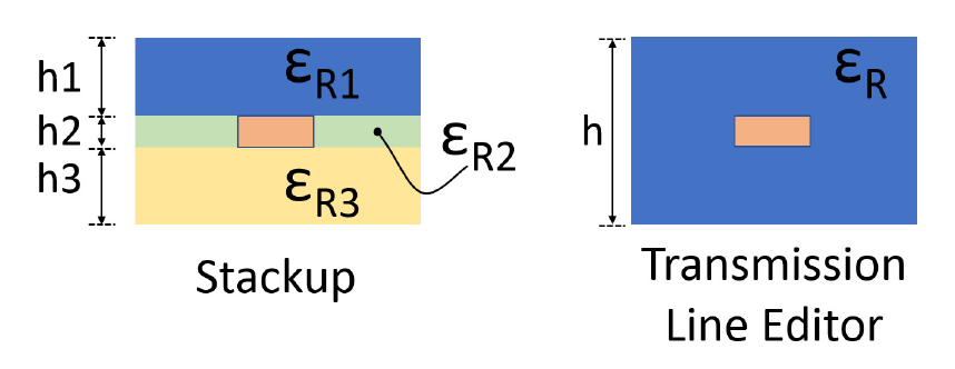
The dielectric constant is a composite and is derived from the stackup by the equation: