Plan Path Using Ackermann MPPI Controller in Simulink
This example demonstrates how to follow an obstacle-free path with an Ackermann vehicle model between two locations on a given map in Simulink®. It uses the RRT* planning algorithm to generate the path and the Ackermann MPPI Controller block to generate control commands for navigating this path. It then simulates the vehicle motion based on those commands using an Ackermann kinematic motion model.
Load Occupancy Map
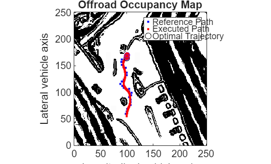
Load the occupancy map, which defines the map limits and obstacles within the environment. This example uses the offroadMap in the exampleHelperPlotMap function.
exampleHelperPlotMap();
![Figure contains an axes object. The axes object with title Offroad Occupancy Map, xlabel X [meters], ylabel Y [meters] contains an object of type image.](../../examples/offroad_autonomy/win64/PlanPathUsingAckermannMPPIControllerInSimulinkExample_01.png)
The exampleHelperPlotMap function is a utility that loads an occupancy map from a .mat file, such as occupancyMapData.mat, creates a binaryOccupancyMap object, and visualizes it using the plot function. This visualization allows users and developers to verify the environment in which the robot will navigate.
Specify a start and end location within the map.
startLoc = [2 2];
goalLoc = [18 15];
Open Simulink Model
Open the Simulink model to understand its structure.
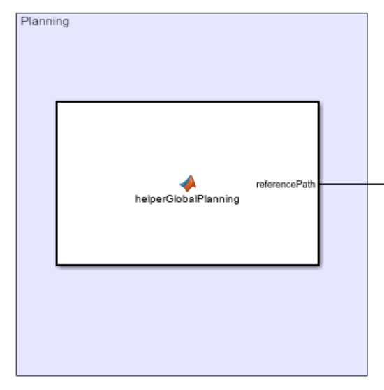
open_system('pathPlanningAckermannMPPI.slx');The model consists of three primary parts:
Planning: The Planner MATLAB Function block implements the RRT* algorithm. It takes the start location, goal location, and map as inputs, then outputs an array of waypoints that guide the vehicle to the goal position.
Path Following: This part consists of two key components:
Ackermann MPPI Controller: The Ackermann MPPI Controller generates the linear and angular velocity commands based on the waypoints and the current vehicle pose.
Has Reached Goal Flag: The
HasReachedGoalflag, output by the Ackermann MPPI Controller block within theSolution Infobus, indicates whether the vehicle has successfully reached the goal. This example uses this flag to stop the simulation upon reaching the goal.
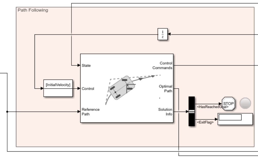
Plant Model: The Plant Model simulates the simplified kinematics of the Ackermann model, applying the velocity commands to drive the system's motion toward the goal.

Visualization: Displays the real-time behavior of the vehicle on the map, including its trajectory and current position.

The Visualization block in the model displays the real-time motion of the vehicle as it navigates the map. It dynamically updates the vehicle's trajectory and position while overlaying the start and goal locations on the occupancy map. The visualization leverages helper functions, such as exampleHelperVisualizeVehicle and exampleHelperVehicleGeometry, to ensure accurate rendering of the vehicle's dimensions and movements.
Run Simulink Model
Visualize the motion of the vehicle as it navigates the map using the simulation results.
simulation = sim('pathPlanningAckermannMPPI.slx');