Simulation and Code Generation of Motion Instructions
You can use Simulink® PLC Coder™ software for the behavioral simulation and structured text code generation for the Rockwell Automation® RSLogix™ motion control instructions.
Workflow for Using Motion Instructions in Model
This workflow uses the Simulate and Generate Structured Text Code for Rockwell Automation Motion Instructions example in the
plccoderdemos folder. This example provides a template that you can use
with motion instructions. It contains the files listed in this table:
| Name | Description |
|---|---|
MotionControllerExample.slx | Simulink model containing an example Stateflow® chart for modeling motion instructions. |
DriveLibrary.slx | Simulink library with a Stateflow chart that is used for modeling a real world drive (axis) with trajectories, delays, and other parameters. |
MotionTypesForSim.mat | MAT file containing the bus data types for the
|
Trajectory.m | MATLAB® class file for implementing trapezoidal velocity profile. This file
is used to simulate the behavior of the |
MotionApiStubs.slx | Supporting file for code generation. |
MotionInstructionType.m | MATLAB enumeration class file that represents the type of motion API calls.
For example, |
plc_keyword_hook.m | Helper file to avoid name mangling and reserved keyword limitations. |
plcgeneratemotionapicode.p | Function that transforms the chart in the model to make it suitable for code generation. |
Before you start, copy the files in the example to the current working folder.
Create a Simulink model with a Stateflow chart.
Load the bus data types from the
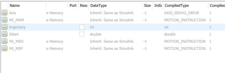
MotionTypesForSim.matfile into the workspace by using theloadfunction.Create data that represents the drive and motion instructions for the chart. For information on adding data to Stateflow charts, see Add Stateflow Data (Stateflow)
Copy the drive(axis) model from the
DriveLibrary.slxfile into the Stateflow chart. You must copy the drive model as an atomic subchart.
The drive logic Stateflow chart models a real world drive with parameters such as trajectory and delay. Any drive subchart has this data:
In the
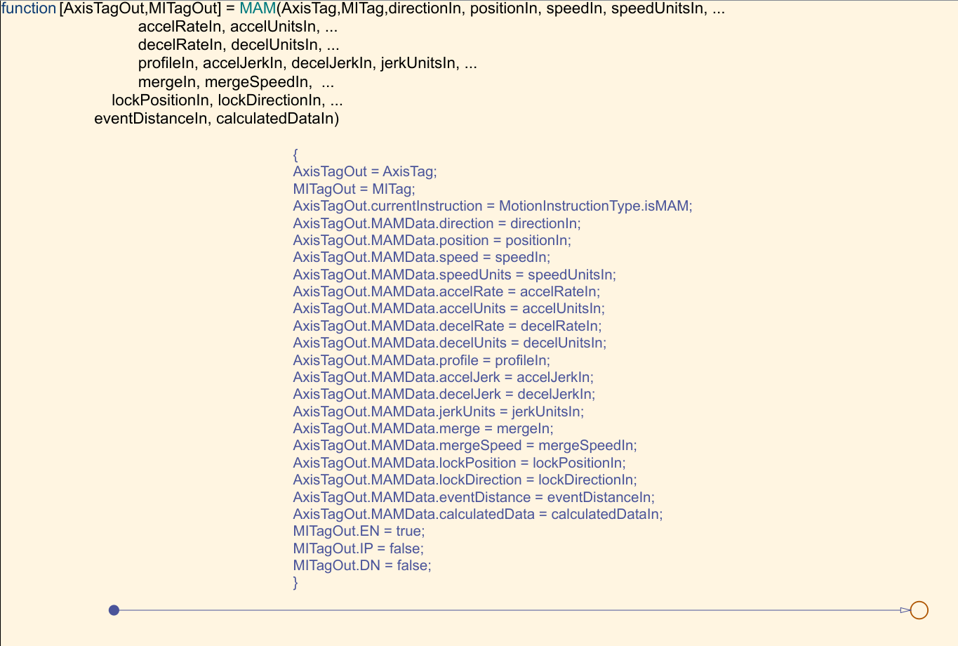
Subchart Mappingsdialog box, to map the drive subchart data store memory data with the local data of the appropriate names in the container chart. For more information, see Map Variables for Atomic Subcharts and Boxes (Stateflow).Use graphical functions to create motion API instructions. For example, for the
Motion Servo On (MSO)instruction: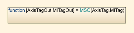

The mapping between the inputs to the outputs is through pass by reference.
Create the controller logic in another subchart and use the motion instructions created in the previous step in the chart. In the example,
Controller1has this Stateflow chart.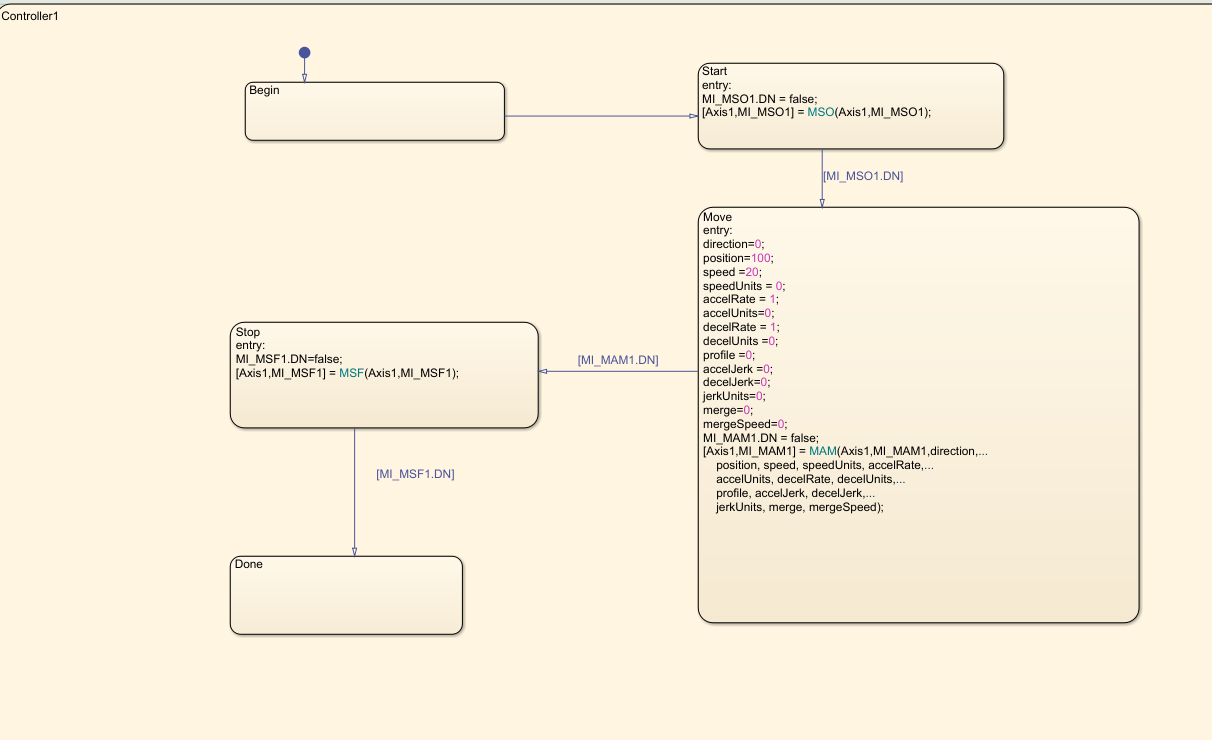
Simulation of Motion API Model
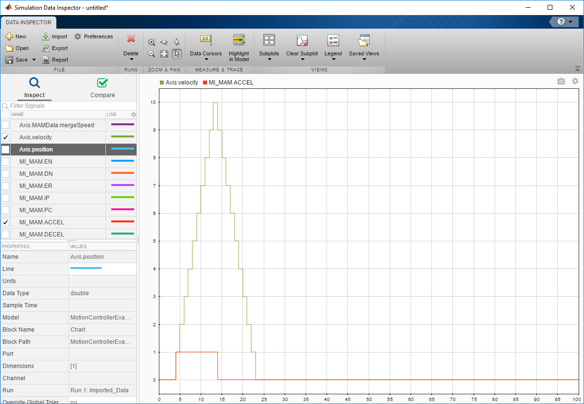
You can run simulation on the model containing the motion instructions and see the state
changes in the controller chart and the Drive subchart. You can also log
the local data of the chart, such as AXIS and the
MOTION_INSTRUCTION variables. For more information, see Log Simulation Output for States and Data (Stateflow).
At the end of simulation, the logged signals are captured in the base workspace as a
variable called logsout. You can import the logged signals into
Simulation Data Inspector. For more information, see View Simulation Data in Simulation Data Inspector.
Structured Text Code Generation
To prepare the model for code generation and generate structured text code, use the
plcgeneratemotionapicode function. The
plcgeneratemotionapicode takes the full path name of subsystem
containing the original chart as an input and creates a model from which you can generate
structured text code.
Add Support for Other Motion Instructions
The plcdemo_motion_api_rockwell example supports only these motion
instructions:
MAMMASMSFMSO
To use other Rockwell Automation
RSLogix motion instructions in the model (for example, Motion Axis Jog
(MAJ)), :
Because the
MAJinstruction is similar toMAMinstruction, create a bus forMAJwith elements similar to that ofMAM. See Type Editor.
Update the
MotionTypesForSim.matfile with the new definitions forMAJDATAandAXIS_SERVO_DRIVE.In the Stateflow chart, create a graphical function representing
MAJ(similar toMAM). Assign the appropriate inputs and outputs.Create a single transition with commands to set the output values.
Remove the transition commands and copy the graphical function to the
MotionApiStubs.slx.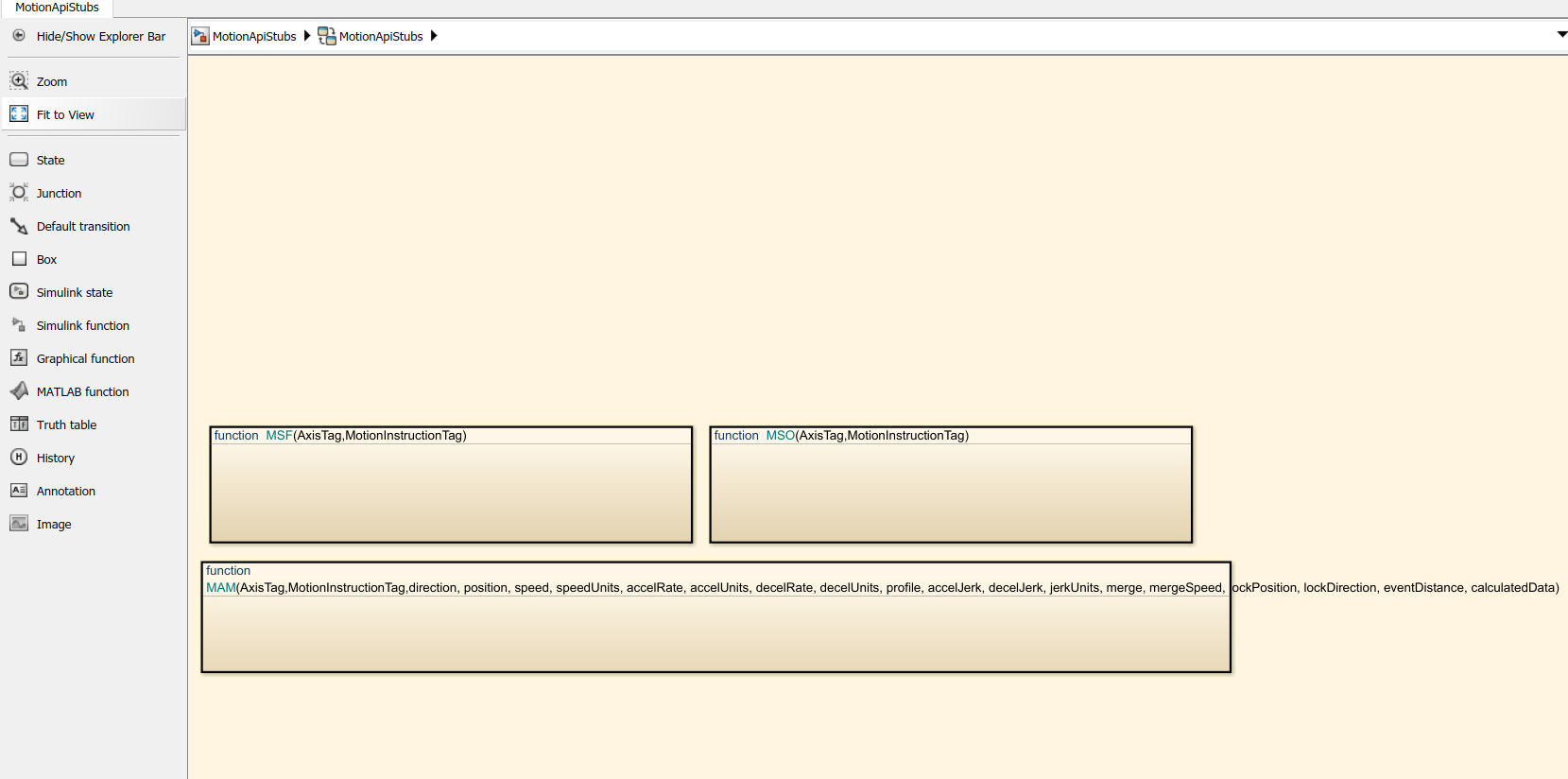
Update the
functionNamevariable in thegetDriveTemplateNames.mfile to includeMAJ.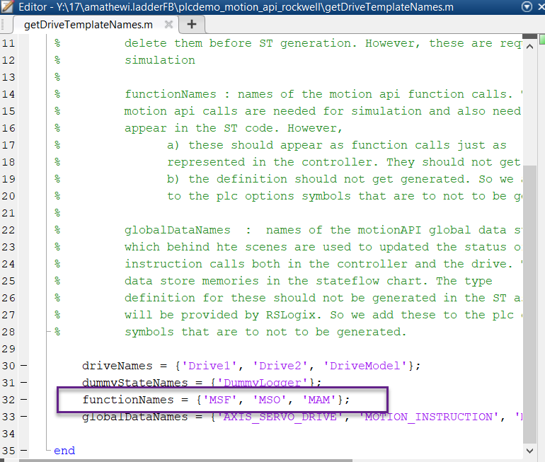
Update the
DriveLibrary.slxfile to respond toMAJcalls during simulation.Create a
isMAJgraphical function (similar toisMAM).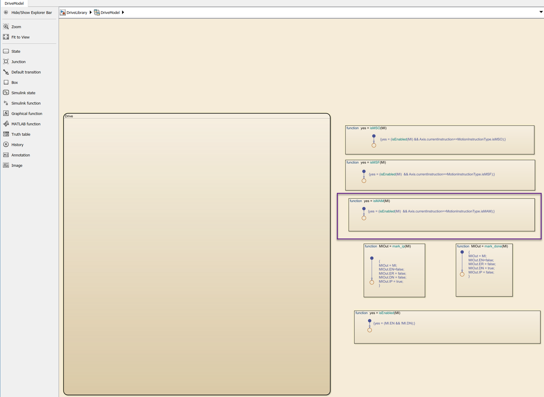
Update the
Drivesubchart to respond toMAJby implementing required transitions etc (similar toMAMas shown).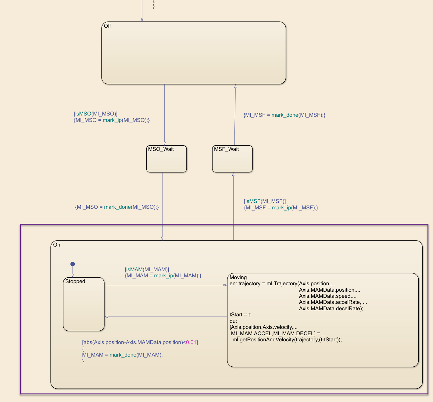
Create or update the controller logic as required. Create a new state and add
MAJinstruction to it (similar to theMAM).
Perform simulation and generate code using the steps described earlier.