Phased Array Gallery
This example shows how to model and visualize a variety of antenna array geometries with Phased Array System Toolbox™. These geometries can also be used to model other kinds of arrays, such hydrophone arrays and microphone arrays. You can view code for each plot, and use it in your own project.
Linear Arrays
Linear antenna arrays can have uniform or nonuniform spacing between elements. This most common linear antenna array is the Uniform Linear Array (ULA).
N = 20;  % Number of elements
D = 0.5; % Element spacing (m)
ula = phased.ULA(N,D);
viewArray(ula,'Title','Uniform Linear Array (ULA)')
set(gca,'CameraViewAngle',4.4);

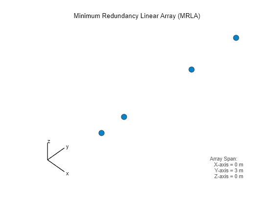
A Minimum Redundancy Linear Array (MRLA) is an example of a nonuniformly spaced linear array. The MRLA minimizes the number of element pairs that have the same spatial correlation lag. It is possible to design a 4-element array whose aperture is equivalent to 7-element ULA.
N = 4;                         % Number of elements
pos = zeros(3,N);
pos(2,:) = [-1.5 -1 0.5 1.5];  % Aperture equivalent to 7-element ULA
mrla = phased.ConformalArray('ElementPosition',pos,...
                           'ElementNormal',zeros(2,N));

viewArray(mrla,'Title','Minimum Redundancy Linear Array (MRLA)')
set(gca,'CameraViewAngle',4.85);
Circular Arrays
Circular antenna arrays can also have uniform or nonuniform spacing between elements. Next is an example of a Uniform Circular Array (UCA).
N = 24;   % Number of elements
R = 1;    % Radius (m)
uca = phased.UCA(N,R);

viewArray(uca,'ShowNormals',true,'Title','Uniform Circular Array (UCA)')
view(0,90)

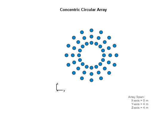
Multiple circular antenna arrays with the same number of elements and different radii form a concentric circular array.
N = 16;                    % Number of elements on each ring
R = [1 1.5 2];             % Radii (m)
azang = (0:N-1)*360/N-180;
pos = [zeros(1,N);cosd(azang);sind(azang)];
elNormal = zeros(2,N);
concentricCircularArray = phased.ConformalArray(...
    'ElementPosition',[R(1)*pos R(2)*pos R(3)*pos],...
    'ElementNormal',[elNormal elNormal elNormal]);

viewArray(concentricCircularArray,'Title','Concentric Circular Array');
Planar Arrays with Rectangular Grid
Planar antenna arrays can have a uniform grid (or lattice) and different boundary shapes. Next is an example of a Uniform Rectangular Array (URA) with a rectangular grid and rectangular boundary.
M = 18;   % Number of elements on each row
N = 16;   % Number of elements on each column
dy = 0.5; % Spacing between elements on each row (m)
dz = 0.5; % Spacing between elements on each column (m)
ura = phased.URA([N M],[dz dy]);

viewArray(ura,'Title','Uniform Rectangular Array (URA)');

You can also model a planar antenna array with a circular boundary. The following code starts with a URA and removes elements outside a circle.
N = 20;   % Number of elements on each row/column of rectangular array
dy = 0.5; % Spacing between elements on each row (m)
dz = 0.5; % Spacing between elements on each column (m)
R = 4.5;  % Radius (m)
refArray = phased.URA(N,[dy,dz]);
pos = getElementPosition(refArray);
elemToRemove = sum(pos.^2)>R^2;
pos(:,elemToRemove) = []; % Exclude elements outside circle
circularPlanarArray = phased.ConformalArray('ElementPosition',pos,...
                           'ElementNormal',zeros(2,size(pos,2)));

viewArray(circularPlanarArray,'Title','Circular Planar Array');

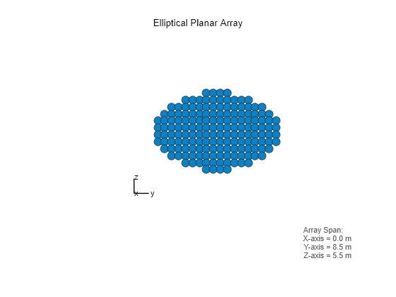
Next is an example of a planar antenna array with an elliptical boundary.
N = 20;   % Number of elements on each row/column of rectangular array
dy = 0.5; % Spacing between elements on each row (m)
dz = 0.5; % Spacing between elements on each column (m)
Ry = 4.5; % Major radius (m)
Rz = 2.8; % Minor radius (m)
refArray = phased.URA(N,[dy,dz]);
pos = getElementPosition(refArray);
elemToRemove = (pos(2,:)/Ry).^2+(pos(3,:)/Rz).^2>1;
pos(:,elemToRemove) = [];  % Exclude elements outside ellipse
ellipticalPlanarArray = phased.ConformalArray('ElementPosition',pos,...
                           'ElementNormal',zeros(2,size(pos,2)));

viewArray(ellipticalPlanarArray,'Title','Elliptical Planar Array');
The next example is a hexagonal array with a rectangular grid.
Nmin = 7;      % Number of elements on bottom row
Nmax = 19;     % Number of elements on widest row
dy = 0.5;      % Row spacing
dz = 0.5;      % Column spacing
rows = [Nmin:2:Nmax Nmax-2:-2:Nmin];
N = sum(rows); % Total number of elements
stop = cumsum(rows);
start = stop-rows+1;
pos = zeros(3,N);
count = 0;
for m = Nmin-Nmax:2:Nmax-Nmin
    count = count+1;
    idx = start(count):stop(count);
    pos(2,idx) = (-(rows(count)-1)/2:(rows(count)-1)/2)*dy;
    pos(3,idx) = m/2*dz;
end
hexagonalPlanarArray = phased.ConformalArray('ElementPosition',pos,...
                           'ElementNormal',zeros(2,N));

viewArray(hexagonalPlanarArray,...
    'Title','Hexagonal Planar Array with Rectangular Grid');

Planar Arrays with Triangular Grid
Triangular grids provide an efficient spatial sampling and are widely used in practice. Here again, different boundary geometries can be applied. First is a rectangular array with a triangular lattice.
M = 18;   % Number of elements on each row
N = 16;   % Number of elements on each column
dy = 0.5; % Spacing between elements on each row (m)
dz = 0.5; % Spacing between elements on each column (m)
rectArrayTriGrid = phased.URA([N M],[dz dy],'Lattice','Triangular');

viewArray(rectArrayTriGrid,...
    'Title','Rectangular Array with Triangular Grid');

Next is a circular planar antenna array with a triangular lattice.
N = 18;   % Number of elements on each row/column of rectangular array
dy = 0.5; % Spacing between elements on each row (m)
dz = 0.5; % Spacing between elements on each column (m)
R = 4.5;  % Radius (m)
refArray = phased.URA(N,[dy,dz],'Lattice','Triangular');
pos = getElementPosition(refArray);
elemToRemove = sum(pos.^2)>R^2;
pos(:,elemToRemove) = []; % Exclude elements outside circle
circularPlanarArrayTriGrid = phased.ConformalArray(...
    'ElementPosition',pos,'ElementNormal',zeros(2,size(pos,2)));

viewArray(circularPlanarArrayTriGrid,...
    'Title','Circular Planar Array with Triangular Grid');

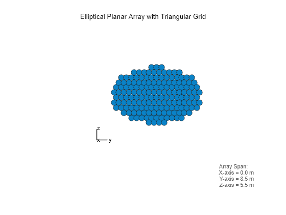
Next is an elliptical planar antenna array with a triangular lattice.
N = 18;   % Number of elements on each row/column of rectangular array
dy = 0.5; % Spacing between elements on each row (m)
dz = 0.5; % Spacing between elements on each column (m)
Ry = 4.5; % Major radius (m)
Rz = 2.8; % Minor radius (m)
refArray = phased.URA(N,[dy,dz],'Lattice','Triangular');
pos = getElementPosition(refArray);
elemToRemove = (pos(2,:)/Ry).^2+(pos(3,:)/Rz).^2>1;
pos(:,elemToRemove) = [];  % Exclude elements outside ellipse
ellipticalPlanarArrayTriGrid = ...
    phased.ConformalArray('ElementPosition',pos,...
    'ElementNormal',zeros(2,size(pos,2)));

viewArray(ellipticalPlanarArrayTriGrid,...
    'Title','Elliptical Planar Array with Triangular Grid');
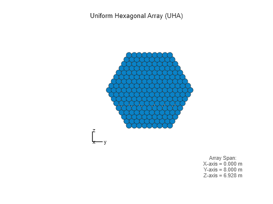
Next is an example of a Uniform Hexagonal Array (UHA).
Nmin = 9;           % Number of elements on bottom row
Nmax = 17;          % Number of elements on mid row
dy = 0.5;           % Row spacing
dz = 0.5*sin(pi/3); % Column spacing
rows = [Nmin:Nmax Nmax-1:-1:Nmin];
N = sum(rows);      % Total number of elements
stop = cumsum(rows);
start = stop-rows+1;
pos = zeros(3,N);
count = 0;
for m = Nmin-Nmax:Nmax-Nmin
    count = count+1;
    idx = start(count):stop(count);
    pos(2,idx) = (-(rows(count)-1)/2:(rows(count)-1)/2)*dy;
    pos(3,idx) = m*dz;
end
uha = phased.ConformalArray('ElementPosition',pos,...
    'ElementNormal',zeros(2,N));

viewArray(uha,'Title','Uniform Hexagonal Array (UHA)');
Thinned Arrays
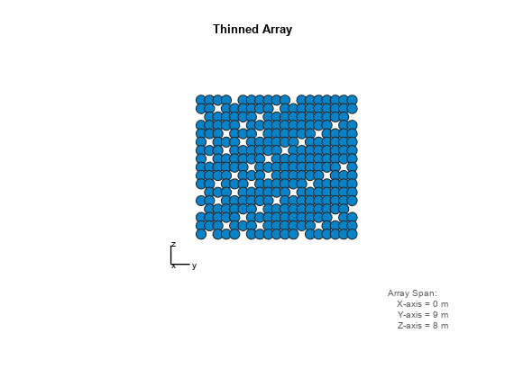
You can also model planar antenna arrays with nonuniform grids. Next is an example of a thinned antenna array.
M = 19;   % Number of elements on each row
N = 17;   % Number of elements on each column
dy = 0.5; % Spacing between elements on each row (m)
dz = 0.5; % Spacing between elements on each column (m)
refArray = phased.URA([N M],[dz dy]);
pos = getElementPosition(refArray);
elemToRemove = [3:11:M*(N-1)/2 M*N-3:-11:(N+1)/2];
pos(:,elemToRemove) = [];
thinnedURA = phased.ConformalArray('ElementPosition',pos,...
                           'ElementNormal',zeros(2,size(pos,2)));

viewArray(thinnedURA,'Title','Thinned Array');
Hemispherical Conformal Arrays
You can also model nonplanar arrays. In many applications, sensors must conform to the shape of the curved surface they are mounted on. Next is an example of an antenna array whose elements are uniformly distributed on a hemisphere.
R = 2;                          % Radius (m)
az = -90:10:90;                 % Azimuth angles
el = -80:10:80;                 % Elevation angles (excluding poles)
[az_grid, el_grid] = meshgrid(az,el);
poles = [0 0; -90 90];          % Add south and north poles
nDir = [poles [az_grid(:) el_grid(:)]']; % Element normal directions
N = size(nDir,2);               % Number of elements
[x, y, z] = sph2cart(degtorad(nDir(1,:)), degtorad(nDir(2,:)),R*ones(1,N));
hemisphericalConformalArray = phased.ConformalArray(...
    'ElementPosition',[x; y; z],'ElementNormal',nDir);

viewArray(hemisphericalConformalArray,...
    'Title','Hemispherical Conformal Array');
view(90,0)

Subarrays
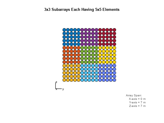
You can model and visualize subarrays. Next is an example of contiguous subarrays.
replicatedURA = phased.ReplicatedSubarray('Subarray',phased.URA(5),...
                               'Layout','Rectangular',...
                               'GridSize',[3 3],'GridSpacing','Auto');

viewArray(replicatedURA,'Title','3x3 Subarrays Each Having 5x5 Elements');
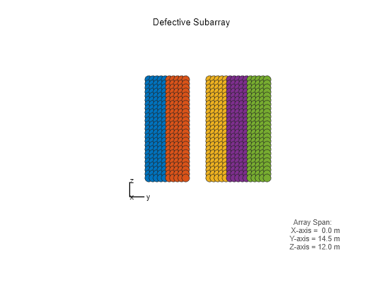
You can lay out subarrays on a nonuniform grid. The next example models the failure of a T/R module for one subarray.
Ns = 6;               % Number of subarrays
posc = zeros(3,Ns);
posc(2,:) = -5:2.5:7.5; % Subarray phase centers
posc(:,3) = [];         % Take out 3rd subarray to model T/R failure
defectiveSubarray = phased.ReplicatedSubarray(...
    'Subarray',phased.URA([25 5]),...
    'Layout','Custom',...
    'SubarrayPosition',posc, ...
    'SubarrayNormal',zeros(2,Ns-1));

viewArray(defectiveSubarray,'Title','Defective Subarray');
view(90,0)
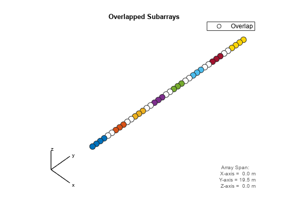
Subarrays can be interlaced and overlapped to mitigate grating lobes.
N = 40;  % Number of elements
Ns = 8;  % Number of subarrays
sel = zeros(Ns,N);
Nsec = N/Ns;
for m = 1:Ns
    if m==1
        sel(m,(m-1)*Nsec+1:m*Nsec+1) = 1;
    elseif m==Ns
        sel(m,(m-1)*Nsec:m*Nsec) = 1;
    else
        sel(m,(m-1)*Nsec:m*Nsec+1) = 1;
    end
end
overlappedSubarray = phased.PartitionedArray('Array',phased.ULA(N),...
    'SubarraySelection', sel);

viewArray(overlappedSubarray,'Title','Overlapped Subarrays');
set(gca,'CameraViewAngle',4.65);
In certain space-constrained applications, such as on satellites, multiple antenna arrays must share the same space. Groups of elements are interleaved, interlaced or interspersed. The next example models interleaved, non-overlapped subarrays.
N = 20;
idx = reshape(randperm(N*N),N,N);
sel = zeros(N,N*N);
for i =1:N,
    sel(i,idx(i,:)) = 1;
end
interleavedArray = phased.PartitionedArray('Array',phased.URA(N),...
    'SubarraySelection',sel);

viewArray(interleavedArray,'Title','Interleaved Arrays');

Another type of nonplanar antenna array is an array with multiple planar faces. The next example shows uniform hexagonal arrays arranged as subarrays on a sphere.
R = 9;                          % Radius (m)
az = unigrid(-180,60,180,'[)'); % Azimuth angles
el = unigrid(-30,60,30);        % Elevation angles (excluding poles)
[az_grid, el_grid] = meshgrid(az,el);
poles = [0 0; -90 90];          % Add south and north poles
nDir = [poles [az_grid(:) el_grid(:)]']; % Subarray normal directions
N = size(nDir,2);               % Number of subarrays
[x, y, z] = sph2cart(degtorad(nDir(1,:)), degtorad(nDir(2,:)),R*ones(1,N));
sphericalHexagonalSubarray = phased.ReplicatedSubarray('Subarray',uha,...
        'Layout','Custom',...
        'SubarrayPosition',[x; y; z], ...
        'SubarrayNormal',nDir);

viewArray(sphericalHexagonalSubarray,...
    'Title','Hexagonal Subarrays on a Sphere');
view(30,0)
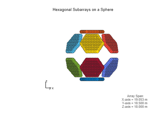
You can also view the array from a different angle and interactively rotate it in 3-D.
view(0,90)
rotate3d on