inldnl
Integral nonlinearity (INL) and differential nonlinearity (DNL) of data converters
Description
s = inldnl(analog,digital,range,type)
The inldnl function only analyzes converters with a finite number
of bits. That means ADCs must have saturation and quantization. The function ignores any
digital value pairs that contain NaN values.
s = inldnl(___,Name,Value)
Note
Initial conditions and other anomalous data can cause this function to behave erratically. This function can analyze nonmonotonic converters, but it cannot handle multiple distinct occurrences of the same code in one transfer function.
Examples
Load the digital input and the analog output of a DAC from MAT files.
load 'digital.mat'
load 'analog.mat'
The nominal analog dynamic range of the DAC is [-1,1]. Turn on plotting for the output converter threshold. Calculate INL and DNL using both best fit and endpoint methods.
inldnl(a,d,[-1 1],'DAC','GenPlotData','on','INLMethod','All','DNLMethod','All')
INLDNL discarded 759 intervals that contained 5062 data points in total.
This made the analog value sets associated with codes [-16, -16, -16, -16, -16, -16, -15, -15, -15, -15, -15, -15, -15, -15, -15, -15, -15, -15, -15, -15, -15, -15, -15, -15, -15, -14, -14, -14, -14, -14, -14, -14, -14, -14, -14, -14, -14, -14, -14, -13, 8, 8, 8, 8, 8, 8, 8, 8, 8, 8, 8, 8, 8, 8, 8, 8, 8, 8, 8, 8, 8, 8, 8, 8, 8, 8, 8, 8, 8, 8, 8, 8, 8, 8, 8, 9, 9, 9, 9, 9, 9, 9, 9, 9, 9, 9, 9, 9, 9, 9, 9, 9, 9, 9, 9, 9, 9, 9, 9, 9, 9, 9, 9, 9, 9, 9, 9, 9, 9, 9, 9, 9, 9, 9, 9, 9, 9, 9, 9, 9, 9, 9, 9, 9, 9, 9, 9, 9, 10, 10, 10, 10, 10, 10, 10, 10, 10, 10, 10, 10, 10, 10, 10, 10, 10, 10, 10, 10, 10, 10, 10, 10, 10, 10, 10, 10, 10, 10, 10, 10, 10, 10, 10, 10, 10, 10, 10, 10, 10, 10, 10, 10, 10, 10, 10, 10, 10, 10, 10, 10, 10, 10, 10, 10, 10, 10, 10, 10, 10, 10, 10, 10, 10, 10, 10, 10, 10, 10, 10, 10, 10, 10, 10, 10, 10, 10, 10, 10, 10, 10, 10, 11, 11, 11, 11, 11, 11, 11, 11, 11, 11, 11, 11, 11, 11, 11, 11, 11, 11, 11, 11, 11, 11, 11, 11, 11, 11, 11, 11, 11, 11, 11, 11, 11, 11, 11, 11, 11, 11, 11, 11, 11, 11, 11, 11, 11, 11, 11, 11, 11, 11, 11, 11, 11, 11, 11, 11, 11, 11, 11, 11, 11, 11, 11, 11, 11, 11, 11, 11, 11, 11, 11, 11, 11, 11, 11, 11, 11, 11, 11, 11, 11, 11, 11, 11, 11, 11, 11, 11, 11, 11, 11, 11, 11, 11, 11, 11, 11, 11, 11, 11, 11, 11, 12, 12, 12, 12, 12, 12, 12, 12, 12, 12, 12, 12, 12, 12, 12, 12, 12, 12, 12, 12, 12, 12, 12, 12, 12, 12, 12, 12, 12, 12, 12, 12, 12, 12, 12, 12, 12, 12, 12, 12, 12, 12, 12, 12, 12, 12, 12, 12, 12, 12, 12, 12, 12, 12, 12, 12, 12, 12, 12, 12, 12, 12, 12, 12, 12, 12, 12, 12, 12, 12, 12, 12, 12, 12, 12, 12, 12, 12, 12, 12, 12, 12, 12, 12, 12, 12, 12, 12, 12, 12, 12, 12, 12, 12, 12, 12, 12, 12, 12, 13, 13, 13, 13, 13, 13, 13, 13, 13, 13, 13, 13, 13, 13, 13, 13, 13, 13, 13, 13, 13, 13, 13, 13, 13, 13, 13, 13, 13, 13, 13, 13, 13, 13, 13, 13, 13, 13, 13, 13, 13, 13, 13, 13, 13, 13, 13, 13, 13, 13, 13, 13, 13, 13, 13, 13, 13, 13, 13, 13, 13, 13, 13, 13, 13, 13, 13, 13, 13, 13, 13, 13, 13, 13, 13, 13, 13, 13, 13, 13, 13, 13, 13, 13, 13, 13, 13, 13, 13, 13, 13, 13, 13, 13, 13, 13, 13, 13, 13, 13, 13, 13, 13, 13, 13, 13, 13, 13, 13, 13, 13, 13, 13, 13, 13, 13, 13, 13, 13, 14, 14, 14, 14, 14, 14, 14, 14, 14, 14, 14, 14, 14, 14, 14, 14, 14, 14, 14, 14, 14, 14, 14, 14, 14, 14, 14, 14, 14, 14, 14, 14, 14, 14, 14, 14, 14, 14, 14, 14, 14, 14, 14, 14, 14, 14, 14, 14, 14, 14, 14, 14, 14, 14, 14, 14, 14, 14, 14, 14, 14, 14, 14, 14, 14, 14, 14, 14, 14, 14, 14, 14, 14, 14, 14, 14, 14, 14, 14, 14, 14, 14, 14, 14, 14, 14, 14, 14, 14, 14, 14, 14, 14, 14, 14, 14, 14, 14, 14, 14, 14, 14, 14, 14, 14, 14, 14, 14, 14, 14, 14, 14, 14, 14, 14, 14, 14, 14, 14, 14, 14, 14, 14, 14, 14, 14, 14, 14, 14, 14, 14, 14, 14, 14, 14, 14, 14, 14, 14, 14, 14, 14, 14, 14, 14, 15, 15, 15, 15, 15, 15, 15, 15, 15, 15, 15, 15, 15, 15, 15, 15, 15, 15, 15, 15, 15, 15, 15, 15, 15, 15, 15, 15, 15, 15, 15, 15, 15, 15, 15, 15, 15, 15, 15, 15, 15, 15, 15, 15, 15, 15, 15, 15, 15, 15, 15, 15, 15, 15, 15, 15, 15, 15, 15, 15, 15, 15, 15, 15, 15, 15, 15, 15, 15, 15, 15, 15, 15, 15, 15, 15, 15, 15, 15, 15, 15, 15, 15] contiguous.

ans = struct with fields:
                Type: 'DAC'
               NBits: 5
                 LSB: 0.0625
        MissingCodes: [0×1 double]
               Codes: [-16 -15 -14 -13 -12 -11 -10 -9 -8 -7 -6 -5 -4 -3 -2 -1 0 1 2 3 4 5 6 7 8 9 10 11 12 13 14 15]
    IdealCodeCenters: [-1 -0.9375 -0.8750 -0.8125 -0.7500 -0.6875 -0.6250 -0.5625 -0.5000 -0.4375 -0.3750 -0.3125 -0.2500 -0.1875 -0.1250 -0.0625 0 0.0625 0.1250 0.1875 0.2500 0.3125 0.3750 0.4375 0.5000 0.5625 0.6250 0.6875 0.7500 0.8125 0.8750 0.9375]
         CodeCenters: [-0.9522 -0.8820 -0.7987 -0.7288 -0.6557 -0.5862 -0.5165 -0.4488 -0.3785 -0.3122 -0.2421 -0.1673 -0.1028 -0.0401 0.0256 0.1009 0.1657 0.2299 0.2963 0.3627 0.4323 0.4956 0.5580 0.6195 0.6536 0.7638 0.8304 0.8970 … ] (1×32 double)
       CodeCenterStD: [0.0246 0.0261 0.0287 0.0280 0.0254 0.0237 0.0207 0.0212 0.0175 0.0177 0.0228 0.0143 0.0106 0.0147 0.0153 0.0228 0.0079 0.0189 0.0107 0.0178 0.0144 0.0109 0.0126 0.0168 0.0116 5.7752e-06 1.1871e-05 9.4212e-06 … ] (1×32 double)
         EndpointINL: [1.7764e-15 0.0661 0.3424 0.4027 0.5151 0.5695 0.6270 0.6522 0.7200 0.7221 0.7866 0.9252 0.8999 0.8462 0.8394 0.9862 0.9666 0.9355 0.9402 0.9447 1.0017 0.9572 0.8977 0.8240 0.3113 1.0180 1.0258 1.0338 -1.0900 -1.0818 -0.0076 0]
          BestFitINL: [-0.6218 -0.5555 -0.2791 -0.2186 -0.1061 -0.0516 0.0061 0.0314 0.0994 0.1016 0.1663 0.3050 0.2799 0.2263 0.2196 0.3665 0.3471 0.3161 0.3210 0.3256 0.3827 0.3384 0.2790 0.2055 -0.3071 0.3997 0.4077 0.4159 -1.7078 … ] (1×32 double)
         EndpointDNL: [0.0661 0.2763 0.0604 0.1124 0.0544 0.0575 0.0252 0.0678 0.0021 0.0645 0.1386 -0.0253 -0.0537 -0.0068 0.1468 -0.0196 -0.0311 0.0047 0.0045 0.0570 -0.0444 -0.0596 -0.0736 -0.5127 0.7067 0.0079 0.0080 -2.1238 0.0082 1.0742 0.0076 0]
          BestFitDNL: [0.0663 0.2764 0.0605 0.1125 0.0545 0.0577 0.0253 0.0680 0.0022 0.0647 0.1387 -0.0251 -0.0536 -0.0067 0.1470 -0.0195 -0.0310 0.0049 0.0047 0.0571 -0.0443 -0.0594 -0.0735 -0.5126 0.7068 0.0080 0.0081 -2.1236 0.0083 1.0743 0.0077 0]
         BestFitPoly: [0.0661 0.1440]
         OffsetError: 0.7641
     OffsetErrorUnit: 'LSB'
           GainError: 1.7843
       GainErrorUnit: 'LSB'
                 TCR: [1×32 struct]
Input Arguments
Name-Value Arguments
Output Arguments
More About
The inldnl function uses the analog-digital pairs to create a
transfer curve representation (TCR) as an array of structures. Each structure has two
entries: analog and digital. The analog entry is a (1×m) or (m×1) vector, and the digital entry is a scalar.
The TCR is created by ordering the analog values from least to greatest, then taking each contiguous analog range belonging to a code value and placing that range of analog values (and the corresponding digital value) in a structure in the TCR. The next structure in the TCR contains the next contiguous range of analog values belonging to a single digital code. As a result, there can be more than one structure in the TCR for any given digital code, and the TCR is ordinal.

The TCR for an example ADC data is shown. The corresponding TCR bin is noted in red.
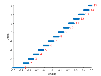
The process for constructing TCR is the same for monotonic or nonmonotonic converters.
Once a TCR is created, the function strategically removes the duplicate bins with the
smallest number until each digital code corresponds to only one bin. After reducing the TCR,
the inldnl function performs analysis on the remaining data.
Version History
Introduced in R2020a
See Also
calibrateADC | calibrateDAC | ADC DC Measurement | SAR ADC | Flash ADC