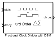
Fractional Clock Divider with DSM
Delta Sigma Modulator based fractional clock divider
Libraries:
Mixed-Signal Blockset /
PLL /
Building Blocks
Description
Using delta sigma (Δ-Σ) modulation technique, a Fractional Clock Divider with DSM reduces the primary fractional spurs by spreading out the range over which the div-by value is varied. This block allows delta sigma modulation of up to 4th order.
Examples
Open the model fractionalClockDivider_w_DSM. The model consists of a Pulse Generator and a Fractional Clock Divider with Accumulator block.
model='fractionalClockDivider_w_DSM';
open_system(model)
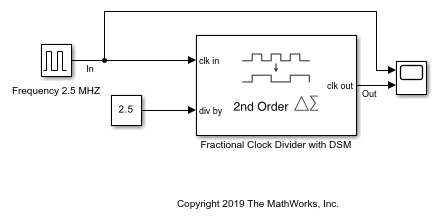
The period of the incoming pulse at the clk in port is 4e-7 s. So, the incoming signal has a frequency of 2.5 MHz. The div-by value is set at 2.5. The clock divider uses a second order delta sigma modulator.
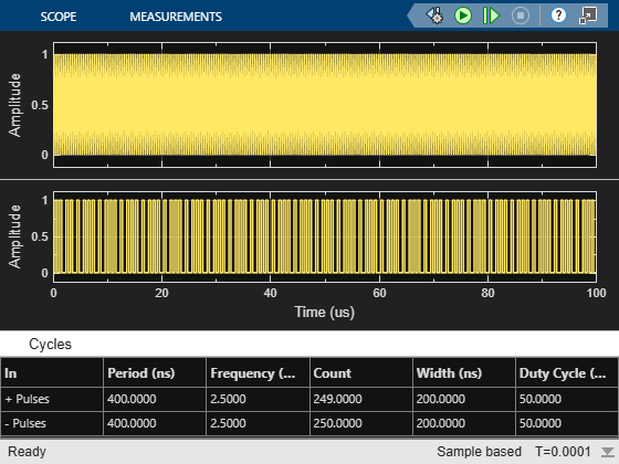
Run the simulation for 1e-4 s. The frequency of the output signal is 1.002 MHz.
sim(model);
Ports
Input
Output
Parameters
More About
References
[1] Miller, B. and Conley, R.J., A Multiple Modulator Fractional Divider. IEEE Transactions on Instrumentation and Measurement, vol. 40, no. 3, 1991, pp. 578-583.
Version History
Introduced in R2019a