Interior PMSM
正弦波逆起電力をもつ三相埋込永久磁石同期モーター

ライブラリ:
Powertrain Blockset /
Propulsion /
Electric Motors and Inverters
Motor Control Blockset /
Electrical Systems /
Motors
説明
Interior PMSM ブロックは、正弦波逆起電力をもつ三相埋込永久磁石同期モーター (PMSM) を実装します。このブロックは三相入力電圧を使用して、個々の相電流を調整し、モーターのトルクや角速度を制御できるようにします。
既定では、このブロックは [シミュレーション タイプ] パラメーターを [連続] に設定して、シミュレーション時に連続サンプル時間を使用します。固定ステップ倍精度および単精度ターゲットのコードを生成する場合は、パラメーターを [離散] に設定することを検討してください。その後、[サンプル時間、Ts] パラメーターを指定します。
[パラメーター] タブで [逆起電力定数 (Ke)] を選択すると、このブロックは次の方程式を実装して永久磁石の鎖交磁束定数を計算します。
モーターの構造
次の図は、回転子に単一の極対があるモーターの構造を示しています。
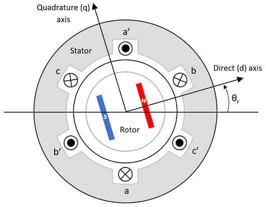
永久磁石によってモーターの磁場が生成され、これによりモーターの角度に基づく正弦波の磁束変化率が得られます。
座標軸の規則で、モーターの角度 θr が 0 の場合に a 相と永久磁石の磁束が揃います。
三相正弦波モデルの電気システム
このブロックは、モーター磁束の基準座標系 (dq 座標系) で表される次の方程式を実装します。モーターの基準座標系のすべての数量は固定子を参照します。
Lq インダクタンスと Ld インダクタンスは、モーターの突極性による相のインダクタンスとモーターの位置の関係を表します。
方程式では次の変数を使用します。
Lq, Ld | q 軸と d 軸のインダクタンス (H) |
R | 固定子巻線の抵抗 (Ω) |
iq, id | q 軸と d 軸の電流 (A) |
vq, vd | q 軸と d 軸の電圧 (V) |
ωm | モーターの機械角速度 (rad/s) |
ωe | モーターの電気角速度 (rad/s) |
λpm | 永久磁石の鎖交磁束定数 (Wb) |
Ke | 逆起電力 (EMF) (Vpk_LL/krpm。ここで、Vpk_LL はピーク電圧の線間の測定値) |
P | 極対数 |
Te | 電磁トルク (Nm) |
Θe | 電気角 (rad) |
機械システム
モーターの角速度は次のように求められます。
方程式では次の変数を使用します。
J | モーターと負荷を合わせた慣性 (kgm^2) |
F | モーターと負荷を合わせた粘性摩擦 (N·m/(rad/s)) |
θm | モーターの機械角度位置 (rad) |
Tm | モーター シャフトのトルク (Nm) |
Te | 電磁トルク (Nm) |
Tf | モーター シャフトの静止摩擦トルク (Nm) |
ωm | モーターの機械角速度 (rad/s) |
動力の考慮
動力を考慮するために、このブロックは次の方程式を実装します。
| バス信号 | 説明 | 変数 | 方程式 | ||
|---|---|---|---|---|---|
|
|
| 機械動力 | Pmot | |
PwrBus | 電力 | Pbus | |||
|
| PwrElecLoss | 抵抗動力損失 | Pelec | ||
PwrMechLoss | 機械動力損失 | Pmech | [機械入力構成] が [機械入力構成] が | ||
|
| PwrMtrStored | 保存されたモーター動力 | Pstr | ||
方程式では次の変数を使用します。
Rs | 固定子の抵抗 (ohm) |
ia, ib, ic | 固定子の a 相、b 相、c 相の電流 (A) |
isq, isd | 固定子の q 軸と d 軸の電流 (A) |
van, vbn, vcn | 固定子の a 相、b 相、c 相の電圧 (V) |
ωm | 回転子の機械角速度 (rad/s) |
F | モーターと負荷を合わせた粘性減衰 (N·m/(rad/s)) |
Te | 電磁トルク (Nm) |
Tf | モーターと負荷を合わせた摩擦トルク (Nm) |
振幅不変 dq 変換
このブロックは次の方程式を使用して、dq と三相振幅が確実に等しくなるようにするための振幅不変 dq 変換を実装します。
方程式では次の変数を使用します。
Θda | 回転子の a 軸に対する dq 固定子電気角 (rad) |
vsq, vsd | 固定子の q 軸と d 軸の電圧 (V) |
isq, isd | 固定子の q 軸と d 軸の電流 (A) |
| va, vb, vc | 固定子の電圧の a 相、b 相、c 相 (V) |
| ia, ib, ic | 固定子の電流の a 相、b 相、c 相 (A) |
端子
入力
出力
パラメーター
ヒント
モーター パラメーターをブロック パラメーターとして指定する代わりに入力端子経由で提供する場合は、PMSM HDL ブロックを使用します。
参照
[1] Kundur, P. Power System Stability and Control. New York, NY: McGraw Hill, 1993.
[2] Anderson, P. M. Analysis of Faulted Power Systems. Hoboken, NJ: Wiley-IEEE Press, 1995.
拡張機能
バージョン履歴
R2017a で導入