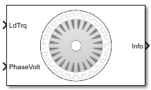
Induction Motor
三相誘導モーター
ライブラリ:
Powertrain Blockset /
Propulsion /
Electric Motors and Inverters
Motor Control Blockset /
Electrical Systems /
Motors
説明
Induction Motor ブロックは、三相誘導モーターを実装します。このブロックは三相入力電圧を使用して、個々の相電流を調整し、モーターのトルクや角速度を制御できるようにします。
メモ
ブロック パラメーターでは、スター等価誘導モーターの各相の値を使用します。
既定では、このブロックは [シミュレーション タイプ] パラメーターを [連続] に設定して、シミュレーション時に連続サンプル時間を使用します。固定ステップ倍精度および単精度ターゲットのコードを生成する場合は、パラメーターを [離散] に設定することを検討してください。その後、[サンプル時間、Ts] パラメーターを指定します。
三相正弦波モデルの電気システム
このブロックは、回転子の静止基準 (dq) 座標系で表される方程式を実装します。d 軸は a 軸と揃っています。回転子の基準座標系のすべての数量は固定子を参照します。
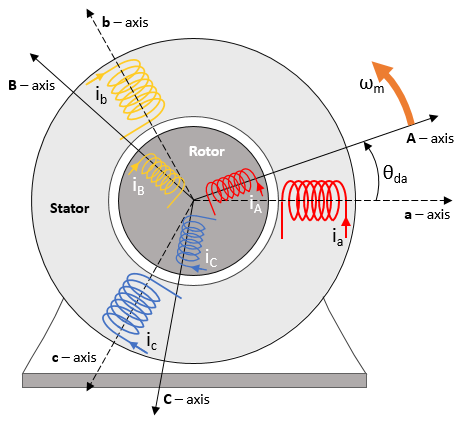
このブロックは次の方程式を使用して、電気角速度 (ωem) と滑り角速度 (ωslip) を計算します。
回転子の A 軸 (dA) に対する dq 回転子電気角速度を計算するために、ブロックは固定子の a 軸 (da) 角速度と滑り角速度の差を使用します。
磁束、電圧、および電流の変換の方程式を単純化するために、ブロックは回転子の A 軸基準座標系を使用します。
| 計算 | 方程式 |
|---|---|
| 磁束 |
|
| 電流 |
|
| インダクタンス |
|
| 電磁トルク |
|
dq と三相電力が確実に等しくなるようにするためのパワー不変 dq 変換 |
|
方程式では次の変数を使用します。
ωm | 回転子の角速度 (rad/s) |
ωem | 回転子の電気角速度 (rad/s) |
ωslip | 回転子の電気滑り角速度 (rad/s) |
ωsyn | 回転子の同期角速度 (rad/s) |
ωda | 固定子の a 軸に対する dq 固定子電気角速度 (rad/s) |
ωdA | 回転子の A 軸に対する dq 固定子電気角速度 (rad/s) |
Θda | 固定子の a 軸に対する dq 固定子電気角 (rad) |
ΘdA | 回転子の A 軸に対する dq 固定子電気角 (rad) |
Lq, Ld | q 軸と d 軸のインダクタンス (H) |
Ls | 固定子のインダクタンス (H) |
Lr | 回転子のインダクタンス (H) |
Lm | 磁化インダクタンス (H) |
Lls | 固定子の漏れインダクタンス (H) |
Llr | 回転子の漏れインダクタンス (H) |
vsq, vsd | 固定子の q 軸と d 軸の電圧 (V) |
isq, isd | 固定子の q 軸と d 軸の電流 (A) |
λsq, λsd | 固定子の q 軸と d 軸の磁束 (Wb) |
irq, ird | 回転子の q 軸と d 軸の電流 (A) |
λrq, λrd | 回転子の q 軸と d 軸の磁束 (Wb) |
| va, vb, vc | 固定子の電圧の a 相、b 相、c 相 (V) |
| ia, ib, ic | 固定子の電流の a 相、b 相、c 相 (A) |
Rs | 固定子巻線の抵抗 (Ω) |
Rr | 回転子巻線の抵抗 (Ω) |
P | 極対数 |
Te | 電磁トルク (Nm) |
機械システム
モーターの角速度は次のように求められます。
方程式では次の変数を使用します。
J | モーターと負荷を合わせた慣性 (kgm^2) |
F | モーターと負荷を合わせた粘性摩擦 (N·m/(rad/s)) |
θm | モーターの機械角度位置 (rad) |
Tm | モーター シャフトのトルク (Nm) |
Te | 電磁トルク (Nm) |
Tf | モーター シャフトの静止摩擦トルク (Nm) |
ωm | モーターの機械角速度 (rad/s) |
動力の考慮
動力を考慮するために、このブロックは次の方程式を実装します。
| バス信号 | 説明 | 変数 | 方程式 | ||
|---|---|---|---|---|---|
|
|
| 機械動力 | Pmot | |
PwrBus | 電力 | Pbus | |||
|
| PwrElecLoss | 抵抗動力損失 | Pelec | ||
PwrMechLoss | 機械動力損失 | Pmech | [機械入力構成] が [機械入力構成] が | ||
|
| PwrMtrStored | 保存されたモーター動力 | Pstr | ||
方程式では次の変数を使用します。
Rs | 固定子の抵抗 (ohm) |
Rr | 回転子の抵抗 (Ω) |
ia, ib, ic | 固定子の a 相、b 相、c 相の電流 (A) |
isq, isd | 固定子の q 軸と d 軸の電流 (A) |
van, vbn, vcn | 固定子の a 相、b 相、c 相の電圧 (V) |
ωm | 回転子の機械角速度 (rad/s) |
F | モーターと負荷を合わせた粘性減衰 (N·m/(rad/s)) |
Te | 電磁トルク (Nm) |
Tf | モーターと負荷を合わせた摩擦トルク (Nm) |
端子
入力
出力
パラメーター
ヒント
モーター パラメーターをブロック パラメーターとして指定する代わりに入力端子経由で提供する場合は、Induction Motor HDL ブロックを使用します。
参照
[1] Mohan, Ned. Advanced Electric Drives: Analysis, Control and Modeling Using Simulink. Minneapolis, MN: MNPERE, 2001.
拡張機能
バージョン履歴
R2020b で導入