Specify Coordinate Conventions for 3D Scenarios
R2026bWhen you create a scenario using the 3D Scenarios add-on, several conventions control how the scenario represents position, orientation, and motion data: reference frame, axes convention, orientation basis, and height reference. Each has a default, but you might need to specify a convention to match your application. Mismatched conventions can produce unexpected or incorrect output values without generating errors or warnings.
Choose a Reference Frame
A reference frame defines how the scenario interprets position and orientation values in
a pose object. The
3D Scenarios add-on supports these reference frames.
| When to Use | Function | Frame Type | Position Format |
|---|---|---|---|
|
You want latitude, longitude, and height coordinates. |
geoframe
| Geographic |
Latitude and longitude coordinates in degrees and height values in meters |
You want Cartesian coordinates that are relative to a local origin in geographic coordinates. |
localframe
| Local Cartesian |
xyz-coordinates in meters |
|
You want Cartesian coordinates that are Earth-centered Earth-fixed (ECEF). |
ecefframe
| ECEF |
xyz-coordinates in meters |
|
You want Cartesian coordinates that are relative to an actor. |
bodyframe
| Body |
xyz-coordinates in meters |
By default, objects in a scenario use the reference frame of the scene, which is
geographic. For a scenario scnro, you can query the default reference
frame by using scnro.Scene.ReferenceFrame.
To represent position and orientation values using a different reference frame, create the reference frame using the geoframe, localframe, ecefframe, or bodyframe function, and then use the reference frame as input to functions such as pose and transform.
This example shows how to get the pose of an actor act with respect to a point in geographic coordinates.
frame = localframe(42.3,-71.1);
p = pose(act,ReferenceFrame=frame);
Set the Axes Convention
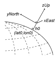
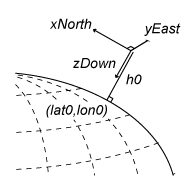
The axes convention controls the order and direction of vectors in a reference frame. Specify the axes convention for a reference frame by using the AxesConvention name-value argument of the geoframe, localframe, and bodyframe functions.
This table shows the axes conventions supported by the geoframe and
localframe functions. For geographic frames, the convention
determines the order of the orientation and motion vectors. For local frames, the
convention also determines the order of the position axes.
| Value | Description | Diagram |
|---|---|---|
"enu" (default) | East-north-up (ENU) axes convention, where the x-axis is east, the y-axis is north, and the z-axis is up. | This diagram illustrates a local frame, where lat0, lon0, and h0 are the coordinates of the local origin.
|
"ned"
| North-east-down (NED) axes convention, where the x-axis is north, the y-axis is east, and the z-axis is down. | This diagram illustrates a local frame, where lat0, lon0, and h0 are the coordinates of the local origin.
|
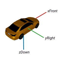
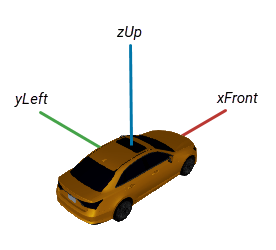
This table shows the axes conventions supported by the bodyframe function. For body frames, the convention determines the order of the position axes, the orientation vectors, and the motion vectors.
| Value | Description | Diagram |
|---|---|---|
"frd" (default) | Forward-right-down (FRD) axes convention, where the x-axis is forward, the y-axis is right, and the z-axis is down. |
|
"flu"
| Forward-left-up (FLU) axes convention, where the x-axis is forward, the y-axis is left, and the z-axis is up. |
|
The ecefframe function uses a fixed "xyz"
convention.
This example shows how to get the pose of an actor act with respect to a point in geographic coordinates, where the position and velocity values use a north-east-down (NED) axes convention.
frame = localframe(42.3,-71.1,AxesConvention="ned");
p = pose(act,ReferenceFrame=frame);
Set the Orientation Basis
You can query the orientation of a pose object as
Euler angles, a direction cosine matrix, or a quaternion by using the euler, dcm, or
quaternion
function, respectively. These orientation values describe the orientation of the actor
relative to the reference frame. The orientation basis determines
whether these orientation values are with respect to the FLU or FRD vector basis. Specify
the orientation basis by using the ObjectOrientationBasis argument of
the euler, dcm, or
quaternion function.
| Value | Description |
|---|---|
"frd"
| The basis vectors use an FRD convention. |
"flu"
| The basis vectors use an FLU convention. |
The default for ObjectOrientationBasis is "auto", which selects a convention based on the AxesConvention property of the reference frame stored in the pose object.
| Reference Frame Convention | Basis Vectors Convention |
|---|---|
"enu"
|
"flu"
|
"ned"
|
"frd"
|
"flu"
|
"flu"
|
"frd"
|
"frd"
|
"xyz"
|
"flu"
|
This example shows how to get Euler angles for an actor act using the FRD convention.
p = pose(act);
eul = euler(p,ObjectOrientationBasis="frd");
Set the Height Reference
The pointtable function creates a geospatial table of points that define geographic positions. You use geospatial tables of points to specify positions for actor creation functions such as aircraft and car, to define waypoints for trajectory creation functions such as airTrajectory and groundTrajectory, and to set actor position using the position function.
When you create a geospatial table of points with height values, the HeightReference argument specifies what surface the height is measured from. The HeightReference argument supports these values.
| Value | Description |
|---|---|
"terrain" (default) | Height values for 3D points are relative to the ground. 2D points are clamped to the ground. |
"ellipsoid"
| Height values for 3D points are relative to the WGS84 ellipsoid. This option requires 3D points. |
"surface"
| Height values for 3D points are relative to the surface of the scenario, which includes terrain and buildings. 2D points are clamped to the surface. |
This diagram shows the relationship between the three height references. The terrain is orange, the ellipsoid is black, and the surface of the scenario is blue. Each point in the diagram has a different height reference.
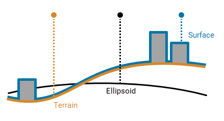
By default, the pointtable function creates 2D points that are
clamped to the ground.
The trajectory creation functions require specific height references:
The
airTrajectoryfunction requires 3D waypoints that are referenced to the ellipsoid.The
groundTrajectoryfunction requires 2D waypoints. To raise an actor above the ground by a fixed offset, use theHeightname-value argument.
This example shows how to add an actor that is 10 meters above the surface to the scenario scnro.
pt = pointtable(42.3,-71.1,10,HeightReference="surface");
c = actor(scnro,pt);
Troubleshoot Unexpected Values
If your code returns unexpected orientation, position, or motion values, check these solutions.
| Issue | Possible Solution |
|---|---|
|
Your |
Verify that the pose object uses the expected axes convention by querying the |
|
Your |
Verify that the pose object uses the expected axes convention by querying the |
|
The values returned by the |
Specify the |
|
The values returned by the |
Specify the |
|
An actor created with |
Specify the |
See Also
pose | ReferenceFrame | pointtable

