PDSCH Port 5 UE-Specific Beamforming
This example demonstrates release 8 port 5 UE-specific beamforming with the LTE Toolbox™.
Introduction
There are seven transmission modes in Release 8:
Single antenna port, port 0
Transmit diversity
Open-loop spatial multiplexing, large-delay Cyclic Delay Diversity (CDD)
Closed-loop spatial multiplexing
Multi-user MIMO
Codebook based beamforming (closed-loop spatial multiplexing using a single transmission layer)
UE-specific beamforming (single antenna port, port 5)
In transmission mode 7, UE-specific beamforming, arbitrary beamforming is applied and the User Equipment (UE) is not notified of the precoding matrix used, therefore the UE needs to estimate the channel including the effect of beamforming. As the UE requires only the UE specific reference signal for demodulation of the Physical Downlink Shared Channel (PDSCH), the data transmission for the UE appears to have been received from only one transmit antenna, therefore, this transmission mode is described as "single-antenna port, port 5".
Transmissions in this scheme are made on a single layer with a single reference signal and can be beamformed onto any number of transmission antennas using any appropriately dimensioned beamforming vector; the choice of the number of transmission antennas and beamforming vector values are not specified in the standard.
This example shows how the "single antenna port, port 5" transmission scheme can be implemented using the LTE Toolbox to transmit and receive a PDSCH. It also demonstrates that the appropriate choice of beamforming vector leads to better performance.
RMC Generator Setup
In this example a Reference Measurement Channel (RMC) configuration is created using lteRMCDL, and reconfigured to describe a UE-specific beamforming configuration. The generation is configured for R.6 and the PDSCH is configured for TxScheme='Port5', the transmission scheme associated with Release 8 UE-specific beamforming in the LTE Toolbox. The number of PDSCH transmission antennas is then set to 4 (The number of columns of the precoding matrix W indicates NTxAnts), indicating that the UE-specific beamforming will beamform onto 4 transmission antennas. Note that rmc.CellRefP=1, meaning that there is only one cell-specific reference signal; this reference signal and associated transmissions that will be mapped onto the first of the 4 transmission antennas.
rmc = lteRMCDL('R.6');         % RMC configuration
rmc.TotSubframes = 1;          % Number of subframes to generate
rmc.PDSCH.TxScheme = 'Port5';  % Set UE-specific beamforming scheme
rmc.PDSCH.CSI = 'On';          % CSI scaling of soft bits
Channel Estimation Configuration
The channel estimation settings are defined using a structure cec. A conservative 9-by-9 pilot averaging window is used to reduce the impact of noise on the channel estimate. Channel estimation is performed using UE-specific reference signals as the Port5 transmission scheme is used.
cec.PilotAverage = 'UserDefined';   % Type of pilot symbol averaging
cec.FreqWindow = 9;                 % Frequency window size
cec.TimeWindow = 9;                 % Time window size
cec.InterpType = 'Cubic';           % 2D interpolation type
cec.InterpWindow = 'Centered';      % Interpolation window type
cec.InterpWinSize = 1;              % Interpolation window size
cec.Reference = 'DMRS';             % Reference for channel estimation
System Processing
The following steps are used to create and receive a UE-specific beamformed PDSCH:
Create a Populated Transmit Resource Grid: A transmit grid is created with cell-specific channels but no PDSCH. To do this,
lteRMCDLToolis used with the 2nd (data) input set to an empty vector. This creates the resource array containing the cell-specific channels of the RMC: Primary Synchronization Signal (PSS), Secondary Synchronization Signal (SSS), Reference Signal (RS), Physical Broadcast Channel (PBCH) and Physical Control Format Indicator Channel (PCFICH). This resource array is mapped to the first transmission antenna within txGrid asCellRefP=1.Set the Beamforming Vector: The beamforming vector
rmc.PDSCH.Wis a field of the PDSCH configuration structure.rmc.PDSCH.Wis a 1-by-NTxAnts (row) vector indicating the complex gains to be applied to the single layer PDSCH transmission and its associated reference signal.Create and Map UE-Specific Reference Signals:
lteDMRSIndicescreates the indices for mapping the UE-specific reference signal onto the transmit resource array.lteDMRScreates the UE-specific reference signal as a column vector (size M-by-1, where M is the number of UE-specific Reference Signals (RS) Resource Elements (REs) in a subframe) which is the same size as the lteDMRSIndices output. Note that as with other precoding operations in the LTE Toolbox (e.g. usinglteDLPrecode), the overall beamforming vectorWis the transpose of what would be expected from the LTE specification i.e. the symbols for layers and antennas lie in columns rather than rows. This is because the LTE Toolbox uses the 2nd (column) rather than 1st (row) dimension to represent transmit antennas (this is consistent with the representation of multichannel signals in MATLAB®).Create and Map the PDSCH:
ltePDSCHIndicescreates the indices for mapping the PDSCH on the one transmission layer and extends these single-layer indices onto all the transmit planes, resulting in anrmc.PDSCH.NTxAnts-column matrix of indices.ltePDSCHscrambles and modulates the random input data provided, resulting in a column vector of modulation symbols, performs beamforming of the column vector by multiplication withrmc.PDSCH.Wto give anrmc.PDSCH.NTxAnts-column matrix, which will be the same size as the ltePDSCHIndices output.Create Transmit Waveform: OFDM modulate the transmit resource grid.
Noisy Propagation Channel Modeling: Channel modeling is performed by multiplying the transmitted waveform
txWaveformwith a fixed channel matrixHof size 1-by-NTxAnts which models reception of the 4-antenna transmission on a single antenna. Note that the transpose operations are required when applying the channel matrixHasHis defined with the typical NRxAnts-by-NTxAnts shape, whereastxWaveformuses the 2nd dimension to represent transmit antennas. Additive noise at 28.0 dB SNR is then applied to the received signal.Synchronization, Demodulation, and Channel Estimation: From the perspective of the receiver, the transmission made using UE-specific beamforming is effectively from a single antenna. Therefore the channel estimation and equalization attempts to estimate and equalize back to the original single transmission layer; the beamforming vector
Wis part of the overall channel responseHW.'that will be estimated and equalized. Therefore channel estimation is performed using the UE-specific reference signals; the 2nd argument provides the PDSCH configuration whenTxScheme='Port5'.PDSCH Reception:
ltePDSCHIndicesprovides matrixindwhich containsrmc.PDSCH.NTxAntscolumns. Only the first column of indices is required as there is only one receive antenna.ltePDSCHDecodeis called to return soft bit estimatesrxBitsalong with the receive symbol constellationrxSymbolswhich is plotted for the case of each of the beamforming vectors. Note that withinltePDSCHDecode, for UE-specific beamforming the receiver will carry out MMSE equalization across the receive antennas, to perform diversity combining (in this example there is only one receive antenna).
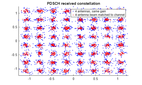
This example runs twice in a loop, the first iteration shows the PDSCH receive constellation when transmitting on all four antennas with the same weighting and the second when transmitting on four antennas with a beamforming vector W which is matched to the channel response. In each case a plot of the PDSCH receive constellation is shown. The second constellation exhibits a lower level of noise than the first, indicating better performance.
It is important to note that all the elements of both beamforming vectors have the same magnitude and consequently the transmit antenna powers are the same across all 4 antennas and the total transmit power for either choice of beamforming vector is the same - this means that neither beamforming vector is given an unfair advantage i.e. more transmit power. For the 2nd simulation loop, W was chosen such that the overall channel response is 1: HW.'=1 therefore W=conj(H). For the first simulation loop (i.e. for W=[17 17 17 17]/34), if we compute HW.' the result is (16-4*j)/34, which has a magnitude of sqrt(4/17) which is approximately 0.485. Therefore the beamformer that is matched to the channel has achieved a channel response with a considerably better gain (1 versus approximately 0.485).
% Initialize storage variables for comparison
rxSymbolsStore = cell(1, 2);
WStore = zeros(2, 4);

% Loop for transmitting with and without optimal beamforming
for optimalbeamforming = 0:1

    % Configure random number generators
    rng('default');

    % Set PDSCH beamforming vector
    if (optimalbeamforming)
        % Use beamforming vector matched to channel response
        rmc.PDSCH.W = [17 8-15*1i -8+15*1i 15+8*1i]/34;

    else
        % Use equal transmission gains for each antenna
        rmc.PDSCH.W = [17 17 17 17]/34;
    end

    % Create a resource grid without the PDSCH. PDSCH can be turned off by
    % specifying the transport stream input to be empty
    [~, txGrid, info] = lteRMCDLTool(rmc,[]);

    % Create and map UE-specific reference signals
    rmc.PDSCH.NTxAnts = size(rmc.PDSCH.W,2);
    dmRsIndices = lteDMRSIndices(rmc,rmc.PDSCH);
    dmRsSymbols = lteDMRS(rmc,rmc.PDSCH);
    txGrid(dmRsIndices) = dmRsSymbols;

    % Create and map the PDSCH reference signals
    [pdschIndices, pdschIndicesDims] = ltePDSCHIndices(rmc, rmc.PDSCH, ...
        rmc.PDSCH.PRBSet);
    pdschSymbols = ltePDSCH(rmc, rmc.PDSCH, ...
        randi([0 1], pdschIndicesDims.G, 1));
    txGrid(pdschIndices) = pdschSymbols;

    % OFDM modulate to create a transmit waveform
    txWaveform = lteOFDMModulate(rmc, txGrid);

    % Pass waveform through channel
    H = [17 8+15*1i -8-15*1i 15-8*1i]/34;  % Channel response
    rxWaveform = (H*txWaveform.').';

    % Add AWGN noise
    SNRdB = 28;
    SNR = 10^(SNRdB/20);
    N = 1/(sqrt(2.0*double(info.Nfft))*SNR); % Scale for IFFT gain
    noise = N*complex(randn(size(rxWaveform)), randn(size(rxWaveform)));
    rxWaveform = rxWaveform + noise;

    % Synchronization
    offset = lteDLFrameOffset(rmc,rxWaveform);
    rxWaveform = rxWaveform(1+offset:end,:);

    % OFDM demodulation to recover resource grid
    rxGrid = lteOFDMDemodulate(rmc, rxWaveform);

    % Channel and noise estimation
    [hest, nest] = lteDLChannelEstimate(rmc, rmc.PDSCH, cec, rxGrid);

    % Perform Minimum Mean Squared Error (MMSE) equalization and decode the
    % PDSCH
    ind = ltePDSCHIndices(rmc, rmc.PDSCH, rmc.PDSCH.PRBSet);
    ind = ind(:, 1); % Only use one receive antenna
    [rxBits, rxSymbols] = ltePDSCHDecode(rmc, rmc.PDSCH, rxGrid(ind), ...
        hest(ind), nest);

    % Store received symbols and beamforming vector for comparison
    rxSymbolsStore{optimalbeamforming+1} = rxSymbols;
    WStore(optimalbeamforming+1, :) = rmc.PDSCH.W;

end
Analysis
The performance in the two simulation loops is compared by plotting the received PDSCH constellations and also displaying the combined channel response HW.'. As can be seen from the figure, the system performs better when the beamforming vector has been matched to the channel response. Note that within the LTE specification, no assistance is provided in determining best beamforming vector. Possible approaches to determining the beamforming vector for example would be to exploit channel reciprocity in Time Division Duplex (TDD), or use angle of arrival estimation of the uplink signal in Frequency Division Duplex (FDD).
hUESpecificBeamformingResults(rxSymbolsStore, H, WStore);
4 antennas, same gain, combined channel response HW.': 0.47059-0.11765i
4-antenna beam matched to channel, combined channel response HW.': 1
Appendix
This example uses this helper function.