LTE Parameterization for Waveform Generation and Simulation
This example shows how to parameterize end-to-end simulations and generate static waveforms by using LTE Toolbox™ software. This example focuses on downlink transmissions, but the concepts discussed also apply to uplink transmissions.
Introduction
The LTE Toolbox can be used to generate standard compliant LTE/LTE-Advanced uplink, downlink, and sidelink complex baseband waveforms which could be used for a number of end user applications including end-to-end simulations, static waveform generation, regression testing, and performance analysis. The toolbox provides functions for flexible and easy generation of the full link, tailored to user requirements. Due to the multiple channels and signals in each link, the toolbox also provides a means to generate pre-defined parameter sets corresponding to standard defined measurement channels which can be used as such or can be further modified to parameterize waveform generation and end-to-end simulations. For the downlink, the toolbox includes these pre-defined parameter sets in the form of the Reference Measurement Channels (RMC) defined in TS 36.101 [ 1 ]. This example demonstrates how the lteRMCDL and lteRMCDLTool functions combine to support LTE downlink waveform generation for different user requirements. The corresponding uplink functions are lteRMCUL and lteRMCULTool.
LTE Downlink Parameterization and Waveform Generation Functions
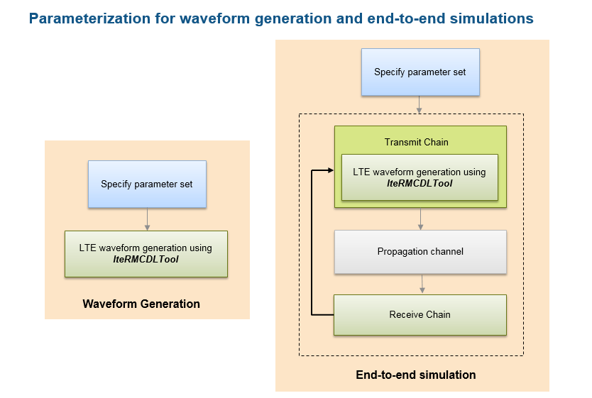
In this example we discuss the two top-level functions provided by the toolbox: lteRMCDL, which creates a full parameter set, and lteRMCDLTool, which generates the downlink waveform. By combining these two functions, standards-compliant LTE waveforms can be generated easily.
The downlink waveform generator function requires a single hierarchical MATLAB® structure which specifies the set of all parameters for the transport channels, physical channels and physical signals present in the output waveform. The generator function returns the time domain waveform, the populated resource grid and the parameter set used in the creation of the waveform.
The toolbox includes the lteRMCDL function, which can provide a fully populated parameter structure for the pre-configured Reference Measurement Channels (RMC) as well as custom configurations. This parameter structure can be directly used by the lteRMCDLTool function to generate the waveforms or it can be used as a template for creating waveforms with user specified values for any of the constituent channels or signals. For example, changing the transmission scheme/mode, modulation scheme, code rate or changing the power level of the physical channels. It is important to note that all the user provided values are defined prior to calling the lteRMCDL function. This is because the lteRMCDL function does not overwrite any parameter values already defined at the input (except for read-only parameters). The following diagram shows parameterization for typical simulation setups.
LTE Downlink Parameterization Options
The LTE Toolbox supports different ways of specifying the parameter set defining the constituent physical channels and signals. These are explained further in subsequent sections:
Create the parameter set from important cell-wide and PDSCH parameters: The
lteRMCDLfunction provides parameter expansion and transport block size processing from cell-wide and PDSCH parameters. All downlink and special (if TDD mode) subframes are assumed to be scheduled. This allows a subset of the parameters to be specified and the function then calculates compatible missing parameters to create the full set. This approach can be used in general to create configurations where subframe 5 is active.Using one of the pre-defined parameter sets: The
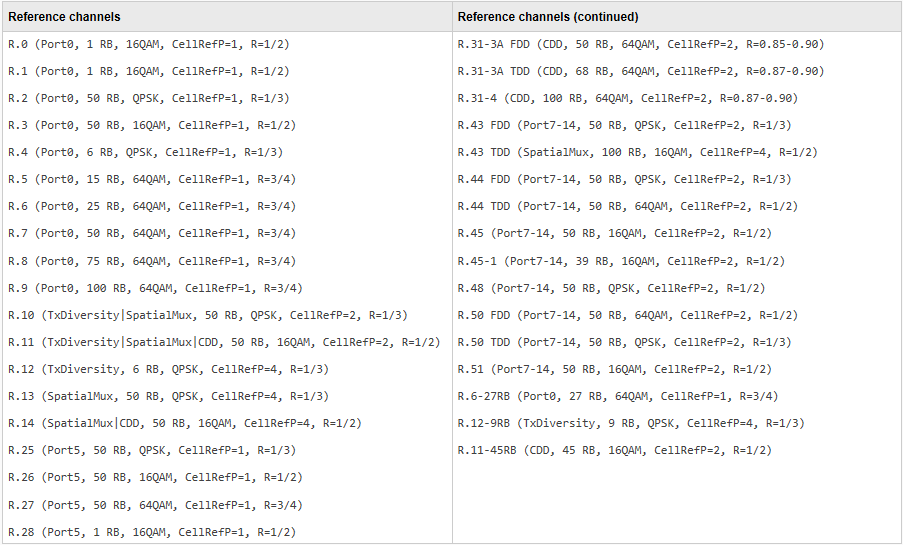
lteRMCDLfunction supports a number of standard defined parameter sets in the form of RMCs. If there is a configuration that exactly matches the requirements or if we want to generate a waveform corresponding to an RMC, we can use that RMC number directly for RMC table lookup and parameter set creation. The RMCs supported and its top-level parameters are shown below:
Customizing one of the pre-defined parameter sets: There are many scenarios where we want a slightly different waveform configuration than given by the pre-defined set. In this case, we can start with one of the pre-defined RMCs and modify parameter(s) which require different values to create the full customized parameter set. This is illustrated by an example in the Parameterization Using Code Rate and Reference PDSCH in Subframe 5 section. Note that the subframes with user data would be as per the RMC. If the
TDDduplex mode is used andTDDConfigis changed to a different value from the RMC, then the behavior of subframe 0, 5, and special subframes will remain unchanged and all other downlink subframes will inherit the properties (i.e. active/nonactive, allocation, target code rate) of subframe 9.
Parameterization Using Important Cell-Wide and PDSCH Parameters
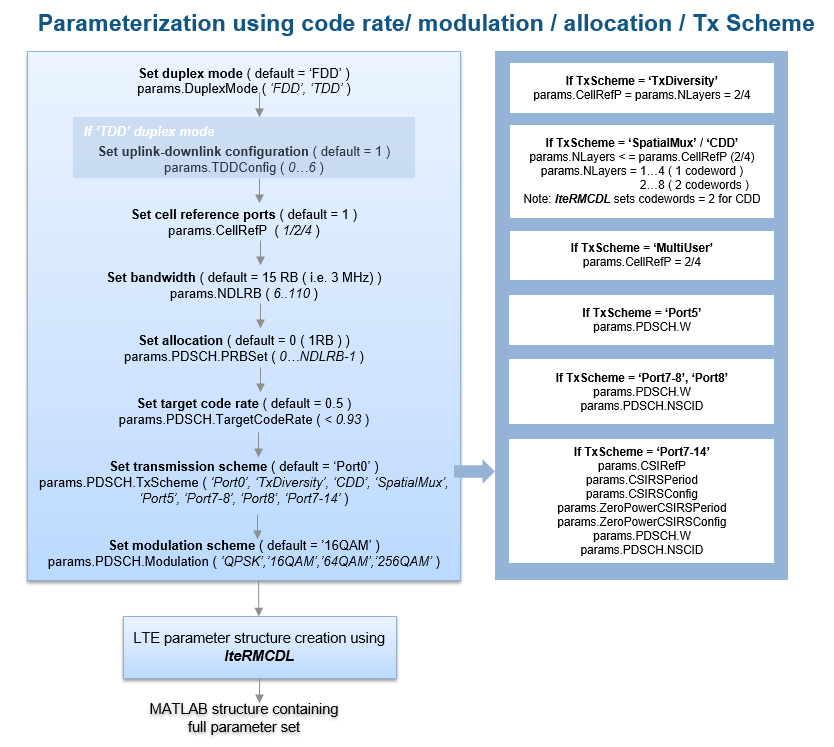
The flow chart below explains how to set up a parameter set using some of the key cell-wide and PDSCH parameters. From a subset of these parameters, the lteRMCDL function can create the full parameter set through parameter expansion.
%  The following example shows how to create a 20MHz, QPSK, 3/4 rate
%  waveform corresponding to transmission mode 8 ('Port7-8' transmission
%  scheme) with full allocation and 2 transmit antennas
dataStream = [1 0 0 1];     % Define the input user data stream
params = struct();          % Initialize the parameter structure
params.NDLRB = 100;         % 20 MHz bandwidth
params.CellRefP = 2;        % Cell reference signals on the first two ports
params.PDSCH.PRBSet = (0:params.NDLRB-1)'; % Full allocation
params.PDSCH.TargetCodeRate = 3/4; % The target code rate
params.PDSCH.TxScheme = 'Port7-8'; % Transmission mode 8
params.PDSCH.NLayers = 2;          % 2 layer transmission
params.PDSCH.Modulation = 'QPSK';  % Modulation scheme
params.PDSCH.NSCID = 0;            % Scrambling identity
params.PDSCH.NTxAnts = 2;          % 2 transmit antennas
params.PDSCH.W = lteCSICodebook(params.PDSCH.NLayers,...
                        params.PDSCH.NTxAnts,0).'; % Precoding matrix

% Now use lteRMCDL to populate other parameter fields.
fullParams = lteRMCDL(params);
% Generate the waveform using the full parameter set.
[dlWaveform, dlGrid, dlParams] = lteRMCDLTool(fullParams,dataStream);
% dlWaveform is the time domain waveform, dlGrid is the resource grid and
% dlParams is the full set of parameters used in the waveform generation.
Parameterization Using Predefined Parameter Set
If there is a predefined parameter set that exactly matches the requirements or if we want to generate a waveform corresponding to an RMC, use that RMC number to create the full parameter set.
To create a waveform corresponding to the R.0 RMC specified in TS 36.101, Annex A.3 [ 1 ].
params = lteRMCDL('R.0'); % Define the parameter set
[dlWaveform, dlGrid, dlParams] = lteRMCDLTool(params,dataStream);

% If the end application is waveform generation, we can also use the RMC
% number directly with the generator to create the waveforms
[dlWaveform, dlGrid, dlParams] = lteRMCDLTool('R.0',dataStream);
Parameterization Using Code Rate and Reference PDSCH in Subframe 5
Suppose we want to define a two codeword full-band 10MHz PDSCH using 2 layer open loop spatial multiplexing, 16QAM modulation and 1/2 rate with reference PDSCH transmission in subframe 5. Looking at TS 36.101 Table A.3.1.1-1: Overview of Downlink reference measurement channels, R.31-3A matches these criteria but with 64QAM modulation and variable code rate.
To create the required parameter set, we start off with the R.31-3A RMC to enable PDSCH transmission in subframe 5. We then override the modulation and code rate. The lteRMCDL function performs the transport block size calculation according to the code rate.
params = struct(); % Initialize the parameter structure
params.RC = 'R.31-3A';
params.PDSCH.TargetCodeRate = 1/2;
params.PDSCH.Modulation = '16QAM';
% Now use lteRMCDL to populate other parameter fields.
fullParams = lteRMCDL(params);
% Generate the waveform using the full parameter set.
[dlWaveform,dlGrid,dlParams] = lteRMCDLTool(fullParams,{dataStream, dataStream}); %#ok<*ASGLU>
Note that we used 'R.31-3A' as a starting point as our required parameter set closely matched this RMC (including reference PDSCH in subframe 5). We can also generate the parameter set by not specifying the RC above (or setting RC to be empty ([])). In this case the parameter set would correspond to reference PDSCH in all downlink and special (if TDD mode) subframes.
Parameterization Using MCS/Transport Block Sizes
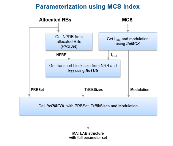
There are cases where we know the MCS or the transport block size and want to create a corresponding waveform. The following figure shows the steps involved in parameterization using MCS.
For example, to create a parameter set for MCS index 10, given the resource allocation is 50 RB:
mcsIndex = 10;
% Get the ITBS and modulation from MCS value
[itbs,modulation] = lteMCS(mcsIndex);
params = struct(); % Initialize the parameter structure
% Bandwidth (NDLRB) must be greater than or equal to allocations
params.NDLRB = 50;                         % Set the bandwidth
params.PDSCH.PRBSet = (0:params.NDLRB-1)'; % Full allocation
params.PDSCH.Modulation = modulation;      % Set the modulation scheme
nrb = size(params.PDSCH.PRBSet,1);         % Get number of RBs allocated
tbs = double(lteTBS(nrb,itbs));            % Get the transport block size
% Now create the 'TrBlkSizes' vector with no transmission in subframe 5
params.PDSCH.TrBlkSizes = [ones(1,5)*tbs 0 ones(1,4)*tbs];
% Now use lteRMCDL to populate other parameter fields.
fullParams = lteRMCDL(params);
% Now generate the waveform using the full parameter set.
[dlWaveform, dlGrid, dlParams] = lteRMCDLTool(fullParams,dataStream);
This approach can also be used to create a parameter set with a transport block size that is not standard defined, or when the required transport block size corresponds to a code rate greater than 0.93 (the standard restricts the code rate to be a maximum of 0.93). For these cases, we can specify the transport block size as shown in the example above and other parameters will be updated accordingly by the lteRMCDL function. Note that RMCs don't typically define a reference PSDCH transmission in subframe 5 because of the possible presence of the SIB1 PDSCH. If a reference PDSCH is required then there are two ways to enable it:
The RMC is specified via the 'RC' field and is either 'R.31-3A' or 'R.31-4'.
The 'RC' field is not present or is specified as empty (e.g. params.RC = []).
Parameterization Using Variable Code Rate and Resource Allocation
The lteRMCDL and lteRMCDLTool functions can be used to generate waveforms where parameters vary over the subframes in a frame (e.g. CFI, PRBSet, TargetCodeRate). The CFI and target code rate can be specified as a vector and PRBSet as a cell array, when the values are changing per subframe.
In this example, we create a waveform corresponding to R.31-3 FDD RMC where the code rate and allocation varies per subframe. This is a two codeword RMC with code rate of 0.61 in subframe 0, 0.62 in subframe 5 and 0.59 in all other subframes. The number of allocated resource blocks are (4...99) in subframe 5 and full bandwidth (0...99) in all other subframes.
params = struct();            % Initialize the parameter structure
params.NDLRB = 100;           % Set the bandwidth (20 MHz)
params.CellRefP = 2;          % Set the cell-specific reference signal ports
params.CFI = 1;               % 1 symbol allocated to PDCCH
params.PDSCH.PRBSet = {(0:99)' (0:99)' (0:99)' (0:99)' (0:99)'  ...
                       (4:99)' (0:99)' (0:99)' (0:99)' (0:99)'};
params.PDSCH.TargetCodeRate = [0.61 0.59 0.59 0.59 0.59 0.62 0.59 0.59 0.59 0.59];
params.PDSCH.TxScheme = 'CDD';% 2 codeword closed loop spatial mux
params.PDSCH.NLayers = 2;     % 1 layer per codeword
params.PDSCH.Modulation = {'64QAM', '64QAM'};% Set the modulation for 2 codewords

% Use lteRMCDL to populate other parameter fields. The resulting
% 'fullParams' can be manually checked against those given by the R.31-3
% FDD RMC in TS 36.101 Table A.3.9.1-1.
fullParams = lteRMCDL(params);
% Generate the waveform using the full parameter set.
[dlWaveform, dlGrid, dlParams] = lteRMCDLTool(fullParams,{dataStream, dataStream});
References
3GPP TS 36.101 "User Equipment (UE) radio transmission and reception"