Main Content

lteExtractResources

Extract resource elements

Description

[re,reind] = lteExtractResources(ind,grid) extracts resource elements re their indices reind from resource array grid using resource elements indices ind. You can extract resource elements from a resource grid with different dimensionality than the resource grid addressed by the indices. The indices specified and returned are in 1–based linear indexing form. Other indexing options are available. The resource extraction process is further explained in Algorithms.

LTE Toolbox™ generates indices for mapping sequences of physical channel and signal symbols to a resource grid. The software generates these indices using channel- or signal-specific functions and address resource elements in an array of size M-by-N-by-P. M is the number of subcarriers, N is the number of OFDM or SC-FDMA symbols and P is the number of planes. The diagram highlights the resource elements of a resource grid addressed by indices, ind. The indices are in a 1–based linear indexing form. P = 2 is the number of antenna ports.

Indexed and unindexed resource elements shared between two antenna ports

Typically the resource array extracts resource elements from one of the following:

  • A 3-D received grid, sized M-by-N-by-NRxAnts. NRxAnts is the number of receive antennas. This grid is created after OFDM or SC-FDMA demodulation.

  • A 4-D channel estimation grid, sized M-by-N-by-NRxAnts-by-P. This grid is created by channel estimation functions (refer Channel Estimation).

You can describe the size of the 3- D received grid as a 4-D grid that has a trailing singleton dimension.

[re1,...,reK,reind1,...,reindK] = lteExtractResources(ind,grid1,...,gridK) extracts resource elements from K resource arrays by using the specified resource element indices.

example

re = lteExtractResources(___,opts) specifies the format of the indices and the extraction method used with a cell array of options, opts.

Examples

collapse all

Extract PDCCH symbols from a received grid and associated channel estimates in preparation for decoding.

Create a transmit waveform for one subframe.

enb = lteRMCDL('R.12');
enb.TotSubframes = 1;
txWaveform = lteRMCDLTool(enb,[1;0;0;1]);

Receive sum of transmit antenna waveforms on three receive antennas.

NRxAnts = 3;
rxWaveform = repmat(sum(txWaveform,2),1,NRxAnts);
rxGrid = lteOFDMDemodulate(enb,rxWaveform);

Compute the channel estimation.

cec.FreqWindow = 1;
cec.TimeWindow = 1;
cec.InterpType = 'cubic';
cec.PilotAverage = 'UserDefined';
cec.InterpWinSize = 3;
cec.InterpWindow = 'Causal';
[hEstGrid,nEst] = lteDLChannelEstimate(enb,cec,rxGrid);

Generate PDCCH indices and extract symbols from received and channel estimate grids in preparation for PDCCH decoding.

ind = ltePDCCHIndices(enb);
[pdcchRxSym,pdcchHestSym] = lteExtractResources(ind,rxGrid,hEstGrid);

pdcchRxSym is sized NRE-by-NRxAnts and pdcchHestSym is sized NRE-by-NRxAnts-by-CellRefP.

rxSymSize = size(pdcchRxSym)
rxSymSize = 1×2

   212     3

hestSymSize = size(pdcchHestSym)
hestSymSize = 1×3

   212     3     4

Decode PDCCH with extracted resource elements.

pdcchBits = ltePDCCHDecode(enb,pdcchRxSym,pdcchHestSym,nEst);

Extract resources from a 3D receive grid and 4D channel estimate grid. Show the location of the indices within the grid.

Setup sizes of the grids: [M N P] and [M N NRxAnts P], where M is the number of subcarriers, N is the number of OFDM symbols, NRxAnts is the number of rx antennas, and P is the number of tx antennas.

M = 4;
N = 4;
P = 2;
NRxAnts = 3;

Create indices and show the locations within the transmit grid addressed by these indices. As you will notice, different resource elements are addressed on each antenna port. Addressed resource element locations contain 1.

ind = [6 22; 16 29];
txGrid = zeros(M,N,P);
txGrid(ind) = 1;

Visualize locations of indexed resource elements in the transmit grid.

visualizeGrid = zeros(M+1,N+1,P);
visualizeGrid(1:M,1:N,:) = txGrid;

figure

subplot(321)
pcolor(visualizeGrid(:,:,1))
title('Port: 1')
xlabel('N')
ylabel('M')

subplot(323)
pcolor(visualizeGrid(:,:,2))
title('Port: 2')
xlabel('N')
ylabel('M')

Figure contains 2 axes objects. Axes object 1 with title Port: 1, xlabel N, ylabel M contains an object of type surface. Axes object 2 with title Port: 2, xlabel N, ylabel M contains an object of type surface.

Create a 3D received grid to extract resource elements. Extract resource elements from the received grid. Show the locations of these extracted resource elements. Addressed resource element locations contain 1.

rxGrid = zeros(M,N,NRxAnts);

[re, indOut] = lteExtractResources(ind,rxGrid);
rxGrid(indOut) = 1;

Visualize locations of indexed resource elements in the receive grid.

figure
visualizeGrid = zeros(M+1,N+1,NRxAnts);
visualizeGrid(1:M,1:N,:) = rxGrid;

subplot(321)
pcolor(visualizeGrid(:,:,1))
title('Allplanes, RxAnt: 1');
xlabel('N')
ylabel('M')

subplot(323)
pcolor(visualizeGrid(:,:,2))
title('Allplanes, RxAnt: 2')
xlabel('N')
ylabel('M')

subplot(325)
pcolor(visualizeGrid(:,:,3))
title('Allplanes, RxAnt: 3')
xlabel('N')
ylabel('M')

Figure contains 3 axes objects. Axes object 1 with title Allplanes, RxAnt: 1, xlabel N, ylabel M contains an object of type surface. Axes object 2 with title Allplanes, RxAnt: 2, xlabel N, ylabel M contains an object of type surface. Axes object 3 with title Allplanes, RxAnt: 3, xlabel N, ylabel M contains an object of type surface.

Create a 4D channel estimate grid to extract resource elements. Extract resource elements from the channel estimate grid. Show the locations of these extracted resource elements. Addressed resource element locations contain 1.

hEstGrid = zeros(M,N,NRxAnts,P);

[re, indOut] = lteExtractResources(ind,hEstGrid);
hEstGrid(indOut) = 1;

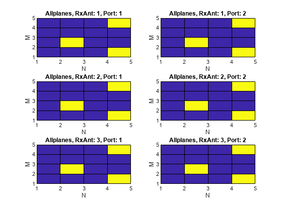
Visualize locations of the resource elements extracted using 'allplanes' mode from 3D receive grid.

figure;
visualizeGrid = zeros(M+1,N+1,NRxAnts,P);
visualizeGrid(1:M,1:N,:,:) = hEstGrid;

subplot(321)
pcolor(visualizeGrid(:,:,1,1))
title('Allplanes, RxAnt: 1, Port: 1')
xlabel('N')
ylabel('M')

subplot(323)
pcolor(visualizeGrid(:,:,2,1))
title('Allplanes, RxAnt: 2, Port: 1')
xlabel('N')
ylabel('M')

subplot(325)
pcolor(visualizeGrid(:,:,3,1))
title('Allplanes, RxAnt: 3, Port: 1')
xlabel('N')
ylabel('M')

subplot(322)
pcolor(visualizeGrid(:,:,1,2))
title('Allplanes, RxAnt: 1, Port: 2')
xlabel('N')
ylabel('M')

subplot(324)
pcolor(visualizeGrid(:,:,2,2))
title('Allplanes, RxAnt: 2, Port: 2')
xlabel('N')
ylabel('M')

subplot(326)
pcolor(visualizeGrid(:,:,3,2))
title('Allplanes, RxAnt: 3, Port: 2')
xlabel('N')
ylabel('M')

Figure contains 6 axes objects. Axes object 1 with title Allplanes, RxAnt: 1, Port: 1, xlabel N, ylabel M contains an object of type surface. Axes object 2 with title Allplanes, RxAnt: 2, Port: 1, xlabel N, ylabel M contains an object of type surface. Axes object 3 with title Allplanes, RxAnt: 3, Port: 1, xlabel N, ylabel M contains an object of type surface. Axes object 4 with title Allplanes, RxAnt: 1, Port: 2, xlabel N, ylabel M contains an object of type surface. Axes object 5 with title Allplanes, RxAnt: 2, Port: 2, xlabel N, ylabel M contains an object of type surface. Axes object 6 with title Allplanes, RxAnt: 3, Port: 2, xlabel N, ylabel M contains an object of type surface.

Create a 4D channel estimate grid to extract resource elements. Extract resource elements from the channel estimate grid using 'direct' extraction mode. Show the locations of these extracted resource elements. Addressed resource element locations contain 1.

hEstGridDirect = zeros(M,N,NRxAnts,P);

[re, indOut] = lteExtractResources(ind,hEstGridDirect,'direct');
hEstGridDirect(indOut) = 1;

Visualize locations of the resource elements extracted using 'direct' mode from 4D channel estimate grid.

figure
visualizeGrid = zeros(M+1,N+1,NRxAnts,P);
visualizeGrid(1:M,1:N,:,:) = hEstGridDirect;

subplot(321)
pcolor(visualizeGrid(:,:,1,1))
title('Direct, RxAnt: 1, Port: 1')
xlabel('N')
ylabel('M')

subplot(323)
pcolor(visualizeGrid(:,:,2,1))
title('Direct, RxAnt: 1, Port: 1')
xlabel('N')
ylabel('M')

subplot(325)
pcolor(visualizeGrid(:,:,3,1))
title('Direct, RxAnt: 1, Port: 1')
xlabel('N')
ylabel('M')

subplot(322)
pcolor(visualizeGrid(:,:,1,2))
title('Direct, RxAnt: 1, Port: 1')
xlabel('N')
ylabel('M')

subplot(324)
pcolor(visualizeGrid(:,:,2,2))
title('Direct, RxAnt: 1, Port: 1')
xlabel('N')
ylabel('M')

subplot(326)
pcolor(visualizeGrid(:,:,3,2))
title('Direct, RxAnt: 1, Port: 1')
xlabel('N')
ylabel('M')

Figure contains 6 axes objects. Axes object 1 with title Direct, RxAnt: 1, Port: 1, xlabel N, ylabel M contains an object of type surface. Axes object 2 with title Direct, RxAnt: 1, Port: 1, xlabel N, ylabel M contains an object of type surface. Axes object 3 with title Direct, RxAnt: 1, Port: 1, xlabel N, ylabel M contains an object of type surface. Axes object 4 with title Direct, RxAnt: 1, Port: 1, xlabel N, ylabel M contains an object of type surface. Axes object 5 with title Direct, RxAnt: 1, Port: 1, xlabel N, ylabel M contains an object of type surface. Axes object 6 with title Direct, RxAnt: 1, Port: 1, xlabel N, ylabel M contains an object of type surface.

Use 'direct' and 'allplanes' extraction methods and subscript indices to extract cell-specific reference signal (CRS) symbols in subcarrier 7 from grid.

Generate a resource grid and CRS indices in the subscript form: [subcarrier, OFDM symbol, CRS port].

enb = lteRMCDL('R.12');
enb.TotSubframes = 1;
enb.CellRefP = 2;
enb.PDSCH.NLayers = 2;
[waveform,grid] = lteRMCDLTool(enb,[1;0;0;1]);
crsInd = lteCellRSIndices(enb,'sub');

There are 2 resource elements used on CRS ports 1 & 2; all are on different OFDM symbols (1, 5, 8, 12).

crsIndSC7 = crsInd(crsInd(:,1)==7,:)
crsIndSC7 = 4x3 uint32 matrix

    7    1    1
    7    8    1
    7    5    2
    7   12    2

Use 'direct' method to extract resource elements. The extracted resource element indices are same as the generated CRS indices as the resource array indexed by crsInd in grid.

[dirREs,dirInd] = lteExtractResources(crsInd,grid,{'direct','sub'});
directIndSC7 = dirInd(dirInd(:,1)==7,:)
directIndSC7 = 4x3 uint32 matrix

    7    1    1
    7    8    1
    7    5    2
    7   12    2

Use 'allplanes' method to extract resource elements. There are 4 extracted CRS indices as per the CRS port on subcarrier 7. Indices addressing unique OFDM symbols in the indexed resource grid are used to extract resource elements from all the CRS ports in 'grid. Therefore indices are extracted at OFDM symbols (1, 5, 8,12) on both CRS ports.

[apREs,apInd] = lteExtractResources(crsInd,grid,{'allplanes','sub'});
allPlanesIndSC7 = apInd(apInd(:,1)==7,:)
allPlanesIndSC7 = 8x3 uint32 matrix

    7    1    1
    7    8    1
    7    5    1
    7   12    1
    7    1    2
    7    8    2
    7    5    2
    7   12    2

Input Arguments

collapse all

Resource elements indices, specified as a numeric array. The indices address elements of a N-by-M-by-P resource array. M is the number of subcarriers, N is the number of OFDM or SC-FDMA symbols, and P is the number of planes.

If you specify an element of this array as a value greater than the number of elements in the grid input, the function uses the value of mod(ind,numel(grid)).

Resource array, specified as a 3-D or 4-D numeric array. Typically the resource array to extract resource elements from in one of the following:

  • A 3–D received grid, sized M-by-N-by-NRxAnts. NRxAnts is the number of receive antennas. This grid is created after OFDM or SC-FDMA demodulation.

  • A 4–D channel estimation grid, sized M-by-N-by-NRxAnts-by-P. This grid is created by channel estimation functions (refer Channel Estimation).

You can describe the size of the 3D received grid as a 4D grid that has a trailing singleton dimension.

Data Types: double

Resource elements extraction options, specified as a character vector, cell array of character vectors, or string array. Values for opts when specified as a character vector include (use double quotes for string):

Parameter FieldRequired or OptionalValuesDescription
Indexing StyleRequired'ind' (default) or 'sub'

Indexing style of the specified or returned indices, ind and reind, specified as one of the following options:

  • 'ind' — linear index form

  • 'sub' — subscript form

Index BaseRequired'1based' (default) or '0based'

Base value of the specified or returned indices, ind and reind, specified as one of the following options:

  • '1based' — the first value of index sequence is one

  • '0based' — the first value of the index sequence is zero

Extraction MethodRequired'allplanes' (default) or 'direct'

Resource element extraction methods. The methods are described in Algorithms.

  • 'allplanes' — uses indices addressing unique subcarrier and symbol location over all planes of the indexed resource array for extraction.

  • 'direct' — only resource elements relevant to each plane of the indexed resource grid are extracted.

Output Arguments

collapse all

Extracted resource elements, returned as a column vector or numeric array.

When 'allplanes' extraction method is used, the extracted resource elements array is of size NRE-by-NRxAnts-by-P where:

  • NRE is the number of resource elements per M-by-N plane of grid.

  • M is the number of subcarriers.

  • N is the number of OFDM or SC-FDMA symbols.

  • P is the number of planes.

When using 'direct' extraction method, the size of the extracted resource elements array, re, depends on the number of indices addressing each plane of the indexed source grid:

  • If the same number of indices address each plane then re is of size NRE-by-NRxAnts-by-P.

  • If a different number of indices address each plane then re is a column vector containing all extracted resource elements.

Indices of extracted resource elements within grid, returned as numeric array. reind is the same size as extracted resource elements array re.

Algorithms

collapse all

lteExtractResources extracts resource elements using one of two methods. The 'allplanes' method is the default. You can optionally specify the 'direct' extraction method.

All Planes Extraction Method

The 'allplanes' method extracts resource elements from each M-by-N plane within grid using indices that address unique subcarrier and symbol locations over all the planes of the indexed resource array.

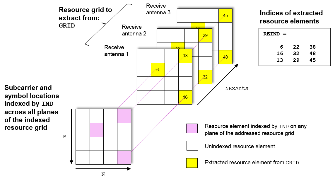
The following diagrams show the resource extraction process for a 3D received grid and a 4D channel estimation grid. The Extract Resources From 3D Receive Grid and 4D Channel Estimate Grid example recreates these diagrams.

The extraction uses indices addressed by unique subcarrier and symbol locations across all planes of the indexed resource grid. The diagram highlights the indices used to extract resource elements addressed on a resource grid with P = 2. P is the number of antenna ports.

Resource extraction for the all planes method, with two antenna ports

The function extracts resource elements from grid at the symbol and subcarrier locations. The following diagrams show the resource element extraction from a 3D received grid grid with NRxAnts = 3.

Resource extraction for the all planes method, with three receive antennas

The following diagram shows the extraction process for a 4D channel estimate grid, grid, with NRxAnts = 3 and P= 2. The 4D resource grid consists of P M-by-N-by-NRxAnts arrays, each associated with an antenna port. The function extracts resource elements from all planes within these arrays.

Resource extraction for the all planes method and a 4D channel estimate grid

Direct Extraction Method

The 'direct' method extracts resource elements from grid with the assumption that the third and fourth dimensions of the grid represent the same property as the planes of the indexed resource array such as antenna ports, layers, transmit antennas. Therefore, the function extracts only resource elements relevant to each plane of the indexed resource grid:

  • For a 3D grid, the 'direct' method extracts elements from each M-by-N plane of grid using indices addressing the same plane of the indexed resource array. This is the same as the standard MATLAB® operation re = grid(ind). Therefore reind = ind.

  • For a 4D grid, the 'direct' method extracts elements from each M-by-N-by-NRxAnts array of grid using indices addressing the same plane of the indexed resource array. Therefore it is assumed the property represented by the planes of the indexed resource array is the same as the fourth dimension of grid.

The extraction of a 4D estimation grid, grid, using the 'direct' method is shown in the following diagram with NRxAnts = 3 and P= 2, which is the number of antenna ports. The 4D resource grid consists of P M-by-N-by-NRxAnts arrays, each associated with an antenna port. Therefore the function uses indices corresponding to each individual antenna port in the indexed resource array to extract resource elements from each of these arrays. The Extract Resources From 3D Receive Grid and 4D Channel Estimate Grid example creates a version of this diagram.

Extraction of a 4D channel estimation grid using the direct method

Version History

Introduced in R2014b