System-Level Condenser Evaporator (2P-MA)
Heat exchanger based on performance data between two-phase fluid and moist air networks
Since R2021b
Libraries:
Simscape /
Fluids /
Heat Exchangers /
Two-Phase Fluid - Moist Air
Description
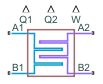
The System-Level Condenser Evaporator (2P-MA) block models a heat exchanger between a two-phase fluid network and a moist air network.
The block can act as a condenser or as an evaporator in a refrigeration system, depending on the direction of heat transfer. The block uses performance data from the heat exchanger datasheet, rather than the detailed geometry of the exchanger. You can adjust the size and performance of the heat exchanger during design iterations, or model heat exchangers with uncommon geometries. You can also use this block to model heat exchangers with a certain level of performance at an early design stage, when detailed geometry data is not yet available.
You parameterize the block by the nominal operating condition. The heat exchanger is sized to match the specified performance at the nominal operating condition at steady state.
The Two-Phase Fluid 1 side approximates the liquid zone, mixture zone, and vapor zone based on the change in enthalpy along the flow path. The Moist Air 2 side models water vapor condensation based on convective water vapor mass transfer with the heat transfer surface. Condensed water is removed from the moist air flow.
This block is similar to the Condenser Evaporator (2P-MA) block, but uses a different parameterization model. The table compares the two blocks:
| Condenser Evaporator (2P-MA) | System-Level Condenser Evaporator (2P-MA) |
|---|---|
| Block parameters are based on the heat exchanger geometry | Block parameters are based on performance and operating conditions |
| Heat exchanger geometry may be limited by the available geometry parameter options | Model is independent of the specific heat exchanger geometry |
| You can adjust the block for different performance requirements by tuning geometry parameters, such as fin sizes and tube lengths | You can adjust the block for different performance requirements by directly specifying the desired heat and mass flow rates |
| You can select between parallel, counter, or cross flow configurations | You can select between parallel, counter, or cross-flow arrangement at nominal operating conditions to help with sizing |
| Predictively accurate results over a wide range of operating conditions, subject to the applicability of the E-NTU equations and the heat transfer coefficient correlations | Very accurate results around the specified operating condition; accuracy may decrease far away from the specified operating conditions |
| Heat transfer calculations account for the variation of temperature along the flow path by using the E-NTU model | Heat transfer calculations approximate the variation of temperature along the flow path by dividing it into three segments |
| Accounts for different fluid properties and heat transfer coefficients for subcooled liquid, liquid-vapor mixture, and superheated vapor | Accounts for different fluid properties and heat transfer coefficients for subcooled liquid, liquid-vapor mixture, and superheated vapor |
| Keeps track of variable zone length fractions for subcooled liquid, liquid-vapor mixture, and superheated vapor regions based on the geometry | Approximates the effect of subcooled liquid, liquid-vapor mixture, and superheated vapor regions using weighting factors based on the difference in enthalpy between inlet and outlet |
| Accounts for water vapor condensation and the latent heat on the moist air flow | Accounts for water vapor condensation and the latent heat on the moist air flow |
Heat Transfer
The block divides the two-phase fluid flow and the moist air flow each into three segments of equal size and calculates heat transfer between the fluids is in each segment. For simplicity, the equation in this section are for one segment.
If you clear the Enable wall thermal mass check box, then the heat balance in the heat exchanger is
where:
Qseg,2P is the heat flow rate from the wall that is the heat transfer surface to the two-phase fluid in the segment.
Qseg,MA is the heat flow rate from the wall to the moist air in the segment.
If you select Enable wall thermal mass, then the heat balance in the heat exchanger is
where:
Mwall is the mass of the wall.
cpwall is the specific heat of the wall.
N = 3 is the number of segments.
Tseg,wall is the average wall temperature in the segment.
t is time.
The heat flow rate from the wall to the two-phase fluid in the segment is
where:
UAseg,2P is the weighted-average heat transfer conductance for the two-phase fluid in the segment.
Tseg,2P is the weighted-average fluid temperature for the two-phase fluid in the segment.
The heat flow rate from the wall to the moist air in the segment is
where:
UAseg,MA is the heat transfer conductance for the moist air in the segment.
is the moist air mixture specific heat per unit mass of dry air and trace gas in the segment.
is the moist air mixture enthalpy per unit mass of dry air and trace gas at the average wall segment temperature.
is the moist air mixture enthalpy per unit mass of dry air and trace gas in the segment.
is the rate of water vapor condensation on the wall surface.
hl,wall is the specific enthalpy of liquid water at the average wall segment temperature.
Using mixture enthalpy in this equation accounts for both differences in temperature and differences in humidity due to condensation [3].
The fluid properties that the block uses in heat transfer calculations are the average between the value at the inlet and the value in the fluid volume.
Note
For the moist air quantities, the bar above the symbols indicates that they are quantities for mixture divided by the mass of dry air and trace gas only, as opposed to dividing by the mass of the whole mixture. The whole mixture includes dry air, water vapor, and trace gas.
Two-Phase Fluid Heat Transfer Correlation
If the segment is subcooled liquid, then the heat transfer conductance is
where:
aL,2P, b2P, and c2P are the coefficients of the Nusselt number correlation. These coefficients are block parameters in the Correlation Coefficients section.
Reseg,L,2P is the average liquid Reynolds number for the segment.
Prseg,L,2P is the average liquid Prandtl number for the segment.
kseg,L,2P is the average liquid thermal conductivity for the segment.
G2P is the geometry scale factor for the two-phase fluid side of the heat exchanger. The block calculates the geometry scale factor so that the total heat transfer over all segments matches the specified performance at the nominal operating conditions.
The average liquid Reynolds number is
where:
is the mass flow rate through the segment.
μseg,L,2P is the average liquid dynamic viscosity for the segment.
Dref,2P is an arbitrary reference diameter.
Sref,2P is an arbitrary reference flow area.
Note
The Dref,2P and Sref,2P terms are included in this equation for unit calculation purposes only, to make Reseg,L,2P nondimensional. The values of Dref,2P and Sref,2P are arbitrary because the G2P calculation overrides these values.
Similarly, if the segment is superheated vapor, then the heat transfer conductance is
where:
aV,2P, b2P, and c2P are the coefficients of the Nusselt number correlation. These coefficients appear as block parameters in the Correlation Coefficients section.
Reseg,V,2P is the average vapor Reynolds number for the segment.
Prseg,V,2P is the average vapor Prandtl number for the segment.
kseg,V,2P is the average vapor thermal conductivity for the segment.
The average vapor Reynolds number is
where μseg,V,2P is the average vapor dynamic viscosity for the segment.
If the segment is liquid-vapor mixture, then the heat transfer conductance is
where:
aM,2P, b2P, and c2P are the coefficients of the Nusselt number correlation. These coefficients appear as block parameters in the Correlation Coefficients section.
Reseg,SL,2P is the saturated liquid Reynolds number for the segment.
Prseg,SL,2P is the saturated liquid Prandtl number for the segment.
kseg,SL,2P is the saturated liquid thermal conductivity for the segment.
CZ is the Cavallini and Zecchin term.
The saturated liquid Reynolds number is
where μseg,SL,2P is the saturated liquid dynamic viscosity for the segment.
The Cavallini and Zecchin term is
where:
νseg,SL,2P is the saturated liquid specific volume for the segment.
νseg,SV,2P is the saturated vapor specific volume for the segment.
xseg,in,2P is the vapor quality at the segment inlet.
xseg,out,2P is the vapor quality at the segment outlet.
The expression is based on the work of Cavallini and Zecchin [5], which derives a heat transfer coefficient correlation at a local vapor quality x. Equations for the liquid-vapor mixture are obtained by averaging Cavallini and Zecchin’s correlation over the segment from xseg,in,2P to xseg,out,2P.
Two-Phase Fluid Weighted Average
The two-phase fluid flow through a segment may not be entirely represented as either subcooled liquid, superheated vapor, or liquid-vapor mixture. Instead, each segment may consist of a combination of these. The block approximates this condition by computing weighting factors (wL, wV, and wM) based on the change in specific enthalpy across the segment and the saturated liquid and vapor specific enthalpies. The block assumes that the specific enthalpy across the segment varies piecewise linearly from inlet to outlet, with the breakpoints corresponding to the saturation boundaries for liquid and vapor. The zone with a larger heat transfer coefficient has a steeper slope than the zone with a lower heat transfer coefficient.
where:
hseg,in,2P is the specific enthalpy at the segment inlet.
hseg,out,2P is the specific enthalpy at the segment outlet.
hseg,SL,2P is the saturated liquid specific enthalpy for the segment.
hseg,SV,2P is the saturated vapor specific enthalpy for the segment.
The weighted-average two-phase fluid heat transfer conductance for the segment is therefore
The weighted-average fluid temperature for the segment is
where:
Tseg,L,2P is the average liquid temperature for the segment.
Tseg,V,2P is the average vapor temperature for the segment.
Tseg,M,2P is the average mixture temperature for the segment, which is the saturated liquid temperature.
Moist Air Heat Transfer Correlation
The heat transfer conductance is
where:
aMA, bMA, and cMA are the coefficients of the Nusselt number correlation. These coefficients are block parameters in the Correlation Coefficients section.
Reseg,MA is the average Reynolds number for the segment.
Prseg,MA is the average Prandtl number for the segment.
kseg,MA is the average thermal conductivity for the segment.
GMA is the geometry scale factor for the moist air side of the heat exchanger. The block calculates the geometry scale factor so that the total heat transfer over all segments matches the specified performance at the nominal operating conditions.
The average Reynolds number is
where:
is the mass flow rate through the segment.
μseg,MA is the average dynamic viscosity for the segment.
Dref,MA is an arbitrary reference diameter.
Sref,MA is an arbitrary reference flow area.
Note
The Dref,MA and Sref,MA terms are included in this equation for unit calculation purposes only, to make Reseg,MA nondimensional. The values of Dref,MA and Sref,MA are arbitrary because the GMA calculation overrides these values.
Moist Air Condensation
The equation describing the heat flow rate from the wall to the moist air in the segment (the last equation in the Heat Transfer section) uses the average moist air mixture enthalpy, , and the wall segment moist air mixture enthalpy, .
The average moist air mixture enthalpy is based on the temperature and humidity of the moist air flow through the segment:
where:
hseg,ag,MA is the average specific enthalpy of dry air and trace gas for the segment.
hseg,w,MA is the average specific enthalpy of water vapor for the segment.
Wseg,MA is the humidity ratio of the segment.
The wall segment moist air mixture enthalpy is based on the temperature and humidity at the wall segment:
where:
hseg,ag,wall is the specific enthalpy of dry air and trace gas at the wall segment temperature.
hseg,w,wall is the specific enthalpy of water vapor at the wall segment temperature.
Wseg,wall is the humidity ratio at the wall segment:
where Wseg,s,wall is the saturated humidity ratio at the wall segment temperature. In other words, the humidity ratio at the wall is the same as the humidity ratio of the moist air flow but not more than the maximum that can be supported at the wall segment temperature.
When Wseg,s,wall < Wseg,MA, water vapor condensation occurs on the wall surface. The rate of water vapor condensation is
The block assumes that the condensed water is drained from the wall surface and is thus removed from the moist air flow downstream.
Pressure Loss
The pressure losses on the two-phase fluid side are
where:
pA,2P and pB,2P are the pressures at ports A1 and B1, respectively.
p2P is internal two-phase fluid pressure at which the heat transfer is calculated.
and are the mass flow rates into ports A1 and B1, respectively.
ρavg,2P is the average two-phase fluid density over all segments.
is the laminar threshold for pressure loss, approximated as 1e-4 of the nominal mass flow rate. The block calculates the pressure loss coefficient, K2P, so that pA,2P – pB,2P matches the nominal pressure loss at the nominal mass flow rate.
The pressure losses on the moist air side are
where:
pA,MA and pB,MA are the pressures at ports A2 and B2, respectively.
pMA is internal moist air pressure at which the heat transfer is calculated.
and are the mass flow rates into ports A2 and B2, respectively.
ρavg,MA is the average moist air density over all segments.
is the laminar threshold for pressure loss, approximated as 1e-4 of the nominal mass flow rate. The block calculates the pressure loss coefficient, KMA, so that pA,MA – pB,MA matches the nominal pressure loss at the nominal mass flow rate.
Two-Phase Fluid Mass and Energy Conservation
The mass conservation equation for the overall two-phase fluid flow is
where:
is the partial derivative of density with respect to pressure for the segment.
is the partial derivative of density with respect to specific internal energy for the segment.
useg,2P is the specific internal energy for the segment.
V2P is the total two-phase fluid volume.
The summation is over all segments.
Note
Although the block divides the two-phase fluid flow into N=3 segments for heat transfer calculations, it assumes all segments are at the same internal pressure, p2P. Consequentially, p2P is outside of the summation.
The energy conservation equation for each segment is
where:
M2P is the total two-phase fluid mass.
and are the mass flow rates into and out of the segment.
Φseg,in,2p and Φseg,out,2p are the energy flow rates into and out of the segment.
The block assumes the mass flow rates between segments are linearly distributed between the values of and .
Moist Air Mass and Energy Conservation
The mass conservation for the overall moist air mixture flow is
where:
is the partial derivative of density with respect to pressure for the segment.
is the partial derivative of density with respect to temperature for the segment.
is the partial derivative of density with respect to specific humidity for the segment.
is the partial derivative of density with respect to trace gas mass fraction for the segment.
xw,seg,MA is the specific humidity, also referred to as the water vapor mass fraction, for the segment.
xg,seg,MA is the trace gas mass fraction for the segment.
VMA is the total moist air volume.
w,seg,conv is the rate of condensation on the wall surface for the segment.
d,seg,evap is the rate of water droplet evaporation for the segment.
The summation is over all segments.
Note
Although the block divides the moist air flow into N=3 segments for heat transfer calculations, it assumes all segments are at the same internal pressure, pMA. Consequentially, pMA is outside of the summation.
The energy conservation equation for each segment is
where:
ua,seg,MA is the dry air specific internal energy for the segment.
ug,seg,MA is the trace gas specific internal energy for the segment.
uw,seg,MA is the water vapor specific internal energy for the segment.
MMA is the total moist air mass.
and are the moist air mass flow rates into and out of the segment.
and are the water vapor mass flow rates into and out of the segment.
and are the trace gas mass flow rates into and out of the segment.
and are the water droplets mass flow rate into and out of the segment.
Rseg is the segment volume specific gas constant.
Φseg,in,MA and Φseg,out,MA are the energy flow rates into and out of the segment.
hd is the water droplet specific enthalpy in the segment.
λd is the value of the Fraction of condensate entrained as water droplets parameter.
The block assumes the mass flow rates between segments are linearly distributed between the values of and .
The water vapor mass conservation equation for each segment is
The trace gas mass conservation equation for each segment is
The water droplet mass balance conservation equation for each segment is
where rd,seg is the mass ratio of the water droplets to the moist air in the fluid volume in the segment.
Note
If the Trace gas model parameter is
None in the Moist Air Properties
(MA) block, the moist air network does not model trace gas. In this
case, in the System-Level Condenser Evaporator (2P-MA) block, the conservation equation for trace gas is set to
0.
If you clear the Enable entrained water droplets in the Moist Air Properties (MA) block, the moist air network does not model entrained water droplets. In this case, in the System-Level Condenser Evaporator (2P-MA) block, the conservation equation for water droplets is set to 0.
Assumptions and Limitations
When determining the heat exchanger size, the block ignores the value of the Fraction of condensate entrained as water droplets parameter and assumes that the condensate is not entrained as droplets.
Examples
Initialize a System-Level Heat Exchanger
Specify the initial conditions for a system-level heat exchanger to prevent transient behavior at the start of the simulation. Properly specifying initial conditions can prevent unwanted behavior at the start of the simulation, such as spikes in values.

Liquid Air Energy Storage System
Models a grid-scale energy storage system based on cryogenic liquid air. When there is excess power, the system liquefies ambient air based on a variation of the Claude cycle. The cold liquid air is stored in a low-pressure insulated tank until needed. When there is high power demand, the system expands the stored liquid air to produce power based on the Rankine cycle.

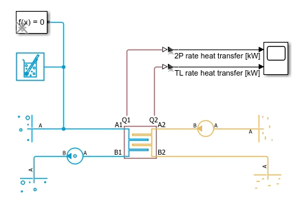
Refrigeration Cycle (Air Conditioning)
A refrigeration cycle for a home air conditioning system. See Model a Refrigeration Cycle for the recommended steps to build this model in the two-phase fluid domain.
Ports
Output
Conserving
Parameters
References
[1] Ashrae Handbook: Fundamentals. Atlanta: Ashrae, 2013.
[2] Çengel, Yunus A. Heat and Mass Transfer: A Practical Approach. 3rd ed. McGraw-Hill Series in Mechanical Engineering. Boston: McGraw-Hill, 2007.
[3] Mitchell, John W., and James E. Braun. Principles of Heating, Ventilation, and Air Conditioning in Buildings. Hoboken, NJ: Wiley, 2013.
[4] Shah, R. K., and Dušan P. Sekulić. Fundamentals of Heat Exchanger Design. Hoboken, NJ: John Wiley & Sons, 2003.
[5] Cavallini, Alberto, and Roberto Zecchin. “A DIMENSIONLESS CORRELATION FOR HEAT TRANSFER IN FORCED CONVECTION CONDENSATION.” In Proceeding of International Heat Transfer Conference 5, 309–13. Tokyo, Japan: Begellhouse, 1974. https://doi.org/10.1615/IHTC5.1220.