Partially Filled Vertical Pipe LP
(To be removed) Partially filled vertical pipe connecting two tanks
The Hydraulics (Isothermal) library will be removed in a future release. Use the Isothermal Liquid library instead.
For more information on updating your models, see Upgrading Hydraulic Models to Use Isothermal Liquid Blocks.
Library
Low-Pressure Blocks
Description
The Partially Filled Vertical Pipe LP block models a vertical pipe connecting two tanks. The block takes into account the possibility that the top tank gets emptied, and therefore the top port of the pipe can be exposed. The fluid level in the pipe then settles at some intermediate position, depending on pressures at both ports.
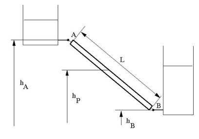
The following schematic diagram shows two tanks connected by a partially filled vertical pipe, where:
hA and hB are the elevations of ports A and B, respectively
hP is the fluid level in the pipe
L is the length of the pipe
The tank is assumed to be empty when fluid volume becomes less than a specified value. If the upstream tank is emptied, the flow rate through port A is assumed to be 0, and the tank pressurization pressure propagates through port A to the pipe. When pressure increases at the bottom port B, the fluid flows upstream. After the pipe is completely filled, the fluid can start filling the top tank.
You must connect port A to a component that provides data on fluid volume (such as the Reservoir block or any of the tank blocks). Port A elevation must be greater than port B elevation.
You can connect port B to any hydraulic component, with one restriction: the component must keep the port submerged at all times.
The pipe hydraulic resistance is proportional to the length of fluid in the pipe (wet length). The shorter the wet length, the lower the resistance. To avoid zero resistance as wet length approaches 0, the volume of fluid in the pipe is limited to the same minimum value as the tank. After the minimum volume is reached, the flow rate through port B is assumed to be 0.
It is a good practice to connect port B either to another tank or to a pressure source. When you connect it to a pressure source, it is good practice to insert some hydraulic resistance (fixed orifice, valve, and so on) between the pipe and the source, to avoid zero resistance.
The block models pipes with circular and noncircular cross sections. The block accounts for friction losses, variable fluid level in the pipe, and resulting variable heads at the ports. The block is based on the assumption of steady-state fluid momentum conditions. For additional information, see Basic Assumptions and Limitations. To account for local resistances (such as bends, fittings, inlet and outlet losses, and so on), convert the resistances into their equivalent lengths, sum up all the resistances to obtain their aggregate length, and then add this length to the pipe geometrical length. The ratio between the added and the current wet length of the pipe is maintained constant as the pipe is emptied or filled with fluid.
Flow rates through the pipe ports are computed individually because they are different when the top port is exposed. The flow rates are proportional to the flow-regime-dependent friction factor and the pressure differential. The friction factor in turbulent regime is determined with the Haaland approximation [1]:
where
| f | Friction factor |
| k | Height of the roughness on the pipe internal surface |
| Re | Reynolds number |
| q | Flow rate |
| DH | Pipe hydraulic diameter |
| A | Pipe cross-sectional area |
| ν | Fluid kinematic viscosity |
At laminar regime, the friction factor is determined as
where s is the geometrical shape factor, or Poiseuille number [1], defined as a function of the Fanning factor for various noncircular shapes: rectangle, concentric annulus, ellipse, and circular sector.
The friction factor during the transition from laminar to turbulent regimes is determined with the linear interpolation between extreme points of the regimes. As a result of these assumptions, the pipe is simulated according to the following equations:
where
| qA, qB | Flow rates through port A and B, respectively |
| pA, pB | Pressures at port A and B, respectively |
| hA, hB | Port A and port B elevations, respectively |
| L | Geometrical pipe length |
| Lad | Aggregate equivalent length of local resistances |
| LF | Pipe wet length |
| Lef | Effective pipe length |
| ρ | Fluid density |
| p | Pressure differential across the pipe |
| V | Fluid volume in the upstream tank |
| Vp | Volume of fluid in the pipe |
| Vmin | Minimum volume of fluid in the tank, or in the pipe. If V becomes less than Vmin, then the upstream tank is considered empty, the flow rate through port A is assumed to be 0, and the tank pressurization pressure propagates through port A to the pipe. If Vp becomes less than Vmin, then the pipe is considered empty and the flow rate through port B is assumed to be 0. |
| hp | Fluid elevation in the pipe |
| Recr | Critical Reynolds number |
| g | Gravity acceleration |
Flow rate A is considered positive when fluid flows into the pipe. Flow rate B is considered positive when fluid flows out of the pipe.
Basic Assumptions and Limitations
The block is based on the assumption of steady-state fluid momentum conditions.
Fluid inertia and fluid compressibility are not taken into account.
Flow is assumed to be fully developed along the pipe length, therefore the end effects are not considered.
To account for local resistances in the pipe, you must convert the resistances into their equivalent lengths, sum them up to obtain their aggregate length, and then add this aggregate length to the pipe geometrical length.
The elevation of port A must be greater than that of port B.
Port A must be connected to the hydraulic port of the top tank. The fluid volume in the top tank must be input into the Partially Filled Vertical Pipe LP block through the physical signal port V. If you use one of the standard Simscape™ Fluids™ reservoir or tank blocks, connect its physical output port directly to the input port V. If you use a custom tank block, it must have a port that exports fluid volume in the tank as a physical signal, and you must connect this output port to the input port V.
Port B must not be exposed.
The friction factor at turbulent regime is computed with the Haaland approximation.
The friction factor at laminar regime is determined as the Poiseuille number divided by the Reynolds number.
The friction factor during transition from laminar to turbulent regime is computed with the linear interpolation.
Parameters
Basic Parameters Tab
- Pipe type
The type of pipe cross section:
CircularorNoncircular. For a circular pipe, you specify its internal diameter. For a noncircular pipe, you specify its hydraulic diameter and pipe cross-sectional area. The default value of the parameter isCircular.- Pipe internal diameter
Pipe internal diameter. The parameter is available if Pipe type is set to
Circular. The default value is0.01m.- Noncircular pipe cross-sectional area
Pipe cross-sectional area. The parameter is available if Pipe type is set to
Noncircular. The default value is0.08m^2.- Noncircular pipe hydraulic diameter
Hydraulic diameter of the pipe cross section. The parameter is available if Pipe type is set to
Noncircular. The default value is0.1m.- Geometrical shape factor
Used for computing friction factor at laminar flow. The shape of the pipe cross section determines the value. For a pipe with a noncircular cross section, set the factor to an appropriate value, for example, 56 for a square, 96 for concentric annulus, 62 for rectangle (2:1), and so on [1]. The default value is
64, which corresponds to a pipe with a circular cross section.- Pipe length
Pipe geometrical length. The default value is
100m.- Aggregate equivalent length of local resistances
Represents total equivalent length of all local resistances associated with the pipe. You can account for the pressure loss caused by local resistances, such as bends, fittings, armature, inlet/outlet losses, and so on, by adding to the pipe geometrical length an aggregate equivalent length of all the local resistances. The default value is
50m.- Tank minimum volume
Minimum volume of fluid in the upstream tank, or in the pipe, corresponding to Vmin in the block equations. The tank or pipe is considered empty if its fluid volume becomes less than Vmin. The default value is
1e-4m^3.- Laminar flow upper margin
Specifies the Reynolds number at which the laminar flow regime is assumed to start converting into turbulent. Mathematically, this is the maximum Reynolds number at fully developed laminar flow. The default value is
2000.- Turbulent flow lower margin
Specifies the Reynolds number at which the turbulent flow regime is assumed to be fully developed. Mathematically, this is the minimum Reynolds number at turbulent flow. The default value is
4000.- Internal surface roughness height
Roughness height on the pipe internal surface. The parameter is typically provided in data sheets or manufacturer catalogs. The default value is
5e-5m.
Vertical Position Tab
- Port A elevation wrt reference plane
The vertical position of the pipe port A with respect to the reference plane. The default value is
50m.- Port B elevation wrt reference plane
The vertical position of the pipe port B with respect to the reference plane. The default value is
0.
Global Parameters
Parameters determined by the type of working fluid:
Fluid density
Fluid kinematic viscosity
Use the Hydraulic Fluid block or the Custom Hydraulic Fluid block to specify the fluid properties.
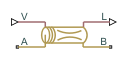
Ports
The block has the following ports:
AHydraulic conserving port associated with the pipe inlet.
BHydraulic conserving port associated with the pipe outlet.
VPhysical signal input port that provides data on fluid volume in the upstream tank.
LPhysical signal output port that exports the pipe fluid level.
References
[1] White, F.M., Viscous Fluid Flow, McGraw-Hill, 1991