Fixed-Displacement Motor (IL)
Fixed-displacement motor in isothermal liquid system

Libraries:
Simscape /
Fluids /
Isothermal Liquid /
Pumps & Motors
Description
The Fixed-Displacement Motor (IL) block models a motor with constant-volume displacement. The fluid may move from port A to port B, called forward mode, or from port B to port A, called reverse mode. Motor mode operation occurs when there is a pressure drop in the direction of the flow. Pump mode operation occurs when there is a pressure gain in the direction of the flow.
Shaft rotation corresponds to the sign of the fluid volume moving through the motor. Positive fluid displacement at corresponds to positive shaft rotation in forward mode. Negative fluid displacement corresponds to negative shaft angular velocity in forward mode.
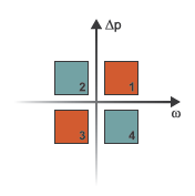
The block has eight modes of operation. The working mode depends on the pressure drop from port A to port B, Δp = pA – pB and the angular velocity, ω = ωR – ωC:
Mode 1, Forward Motor: Flow from port A to port B causes a pressure decrease from A to B and a positive shaft angular velocity.
Mode 2, Reverse Pump: Negative shaft angular velocity causes a pressure increase from port B to port A and flow from B to port A.
Mode 3, Reverse Motor: Flow from port B to port A causes a pressure decrease from B to A and a negative shaft angular velocity.
Mode 4, Forward Pump: Positive shaft angular velocity causes a pressure increase from port A to port B and flow from A to B.
The motor block has analytical, lookup table, and physical signal parameterizations. When using tabulated data or an input signal for parameterization, you can choose to characterize the motor operation based on efficiency or losses.
In the tabulated data and the input signal parameterization options, the threshold parameters Pressure drop threshold for motor-pump transition and Angular velocity threshold for motor-pump transition identify regions where numerically smoothed flow transition between the motor operational modes can occur. Choose a transition region that provides some margin for the transition term, but which is small enough relative to the pressure and angular velocity that it will not impact calculation results.
Analytical Leakage and Friction Parameterization
If you set Leakage and friction parameterization to
Analytical, the block calculates leakage and friction
from constant values of shaft velocity, pressure drop, and friction torque. The
leakage flow rate, which is correlated with the pressure differential over the
motor, is calculated as:
where:
Δp is pA – pB.
ρavg is the average fluid density.
K is the Hagen-Poiseuille coefficient for analytical loss,
where:
D is the value of the Displacement parameter.
ωnom is the value of the Nominal shaft angular velocity parameter.
ηv, nom is the value of the Volumetric efficiency at nominal conditions parameter.
Δpnom is the value of the Nominal pressure drop parameter.
The friction torque, which is correlated with shaft angular velocity, is calculated as:
where:
τ0 is the value of the No-load torque parameter.
k is the friction torque vs. pressure gain coefficient at nominal displacement, which is determined from the value of the Mechanical efficiency at nominal conditions parameter, ηm:
τfric is the friction torque at nominal conditions:
Δp is the pressure drop between ports A and B.
ω is the relative shaft angular velocity, or .
Tabulated Data Parameterizations
When using tabulated data for motor efficiencies or losses, you can provide data for one or more of the motor operational modes. The signs of the tabulated data determine the operational regime of the block. When data is provided for less than four operational modes, the block calculates the complementing data for the other mode(s) by extending the given data into the remaining quadrants.
The leakage flow rate is
where:
and ηv is the volumetric efficiency, which is interpolated from the user-provided tabulated data. The transition term, α, is
where:
Δp is pA – pB.
pthreshold is the value of the Pressure drop threshold for motor-pump transition parameter.
ω is ωR – ωC.
ωthreshold is the value of the Angular velocity threshold for motor-pump transition parameter.
The friction torque is
where:
and ηm is the mechanical efficiency, which is interpolated from the user-provided tabulated data.
The leakage flow rate is
where qloss is interpolated from the Volumetric loss table, q_loss(dp,w) parameter, which is based on user-supplied data for pressure drop, shaft angular velocity, and fluid volumetric displacement.
The shaft friction torque is
where τloss is interpolated from the Mechanical loss table, torque_loss(dp,w) parameter, which is based on user-supplied data for pressure drop and shaft angular velocity.
The block calculates the volumetric loss table, qloss,TLU and the mechanical loss table, τloss,TLU, as
where:
qTLU is the value of the Flow rate vector, q parameter.
ωTLU is the value of the Shaft speed table, w(q,dp) parameter.
ΔpTLU is the value of the Pressure drop vector, dp parameter.
TTLU is the value of the Torque table, T(q,dp) parameter.
If the supplied values for the Shaft speed table, w(q,dp) and Torque table, T(q,dp) parameters do not cover all four quadrants, the block extends the data by
Symmetrically mirroring the values of the Pressure drop vector, dp and Flow rate vector, q parameters to contain negative values.
Symmetrically extending the values of the volumetric loss table, qloss,TLU, to additional quadrants. The signs of these extended values match the sign ΔpTLU in each quadrant.
Calculating the extended values of the shaft speed vector, ωTLU, from the extended values of the flow rate vector and volumetric loss table,
Symmetrically extending the values of the mechanical loss table, τloss,TLU, to additional quadrants. The signs of these extended values match the sign ωTLU in each quadrant.
If your data tables have unknown data points in any of the four corners or the
Shaft speed table, w(q,dp) or Torque table,
T(q,dp) parameters, use NaN in place of these
values. The block fills in the NaN elements in the resulting
volumetric loss table and mechanical loss table with nearest extrapolation with
respect to pressure drop. The block adjusts the signs in the extrapolated
mechanical loss table to match the sign of the corresponding elements in the
shaft speed vector, ωTLU, where
After extending or filling in the unknown data, the block uses linear interpolation and nearest extrapolation to calculate the volumetric and mechanical loss tables during simulation
where
Input Signal Parameterization
When Leakage and friction parameterization is
Input signal - volumetric and mechanical
				efficiencies
, ports EV and
EM are enabled. The internal leakage and shaft friction are
calculated in the same way as the Tabulated data - volumetric and
mechanical efficiencies parameterization, except that
ηv and
ηm are received directly at ports
EV and EM, respectively.
When Leakage and friction parameterization is
Input signal - volumetric and mechanical losses,
ports LV and LM are enabled. These ports
receive leakage flow and friction torque as positive physical signals. The leakage
flow rate is calculated as:
where:
qLV is the leakage flow received at port LV.
pthresh is the value of the Pressure drop threshold for motor-pump transition parameter.
The friction torque is calculated as:
where
τLM is the friction torque received at port LM.
ωthresh is the value of the Angular velocity threshold for motor-pump transition parameter.
The volumetric and mechanical efficiencies range between the user-defined specified minimum and maximum values. Any values lower or higher than this range will take on the minimum and maximum specified values, respectively.
Pump Operation
The motor flow rate is:
where
The motor torque is:
where
The mechanical power extracted by the motor shaft is:
and the motor hydraulic power is:
If you would like to know if the block is operating beyond the
supplied tabulated data, you can set Check if operating beyond the range
of supplied tabulated data to Warning to
receive a warning if this occurs, or Error to stop the
simulation when this occurs. For parameterization by input signal for volumetric or
mechanical losses, you can be notified if the simulation surpasses operating modes
with the Check if operating outside of motor mode
parameter.
You can also monitor motor functionality. Set Check if pressures are
less than motor minimum pressure to
Warning to receive a warning if this occurs, or
Error to stop the simulation when this occurs.
Faults
To model a fault, in the Faults section, click the Add fault hyperlink next to the fault that you want to model. Use the fault parameters to specify the fault properties. For more information about fault modeling, see Introduction to Simscape Faults.
You can model a displacement fault, leakage, or a shaft friction torque fault.
When you enable the Displacement fault parameter, the block scales the displacement by the value of the Faulted displacement factor parameter when the fault triggers,
where fD is the value of the Faulted
displacement factor parameter. When the Leakage and friction
parameterization parameter is Analytical, the
block does not use the faulted displacement value to calculate the Hagen-Poiseuille
coefficient or the friction torque.
When you enable the Leakage fault parameter and Leakage and
friction parameterization is Analytical,
Tabulated data - volumetric and mechanical efficiencies, or
Input signal - volumetric and mechanical efficiencies, the
faulted volumetric efficiency is
where fLeak is the value of the
Faulted leakage factor parameter and
ηv is the volumetric efficiency. When
Leakage and friction parameterization is
Analytical, the block uses the faulted volumetric efficiency
to calculate the Hagen-Poiseuille coefficient.
When Leakage and friction parameterization is Tabulated
data - volumetric and mechanical losses, Input signal -
volumetric and mechanical losses, or Tabulated data - torque
and speed, the faulted leakage volumetric flow rate is
When Leakage and friction parameterization is
Tabulated data - torque
            and speed
, the block calculates
qLeak from the shaft speed and torque
parameters.
When you enable the Shaft friction torque fault parameter and
Leakage and friction parameterization is
Analytical, Tabulated data - volumetric and
mechanical efficiencies, or Input signal - volumetric and
mechanical efficiencies, the faulted mechanical efficiency is
where fFriction is the value
of the Shaft friction torque fault parameter and
ηm is the mechanical efficiency. When
Leakage and friction parameterization is
Analytical, the block uses the faulted mechanical efficiency
to calculate the friction torque.
When Leakage and friction parameterization is Tabulated
data - volumetric and mechanical losses, Input signal -
volumetric and mechanical losses, or Tabulated data - torque
and speed, the faulted friction torque is
When Leakage and friction parameterization is
Tabulated data - torque
            and speed
, the block calculates
τLeak from the shaft speed and torque
parameters.
Examples
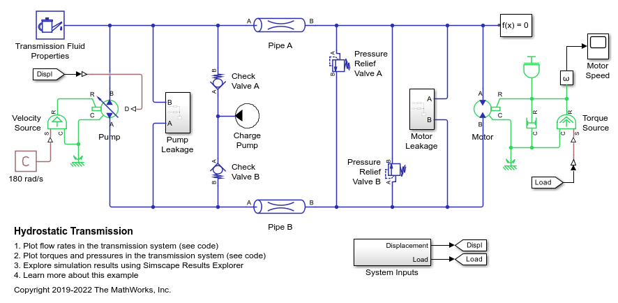
Hydrostatic Transmission
A hydraulic transmission system built of a variable-displacement pump and a fixed-displacement motor. The pipes between the pump and the motor are connected by two replenishing valves (check valves) and a charge pump on the pump side and two pressure relief valves on the motor side. The motor drives a mechanical load consisting of an inertia, viscous friction, and time-varying torque. The system is tested with both positive and negative pump flow rate by varying the pump displacement.
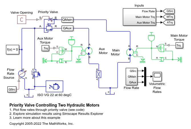
Priority Valve Controlling Two Hydraulic Motors
A pressure-compensated 3-way flow control valve. This valve maintains constant flow rate through the main hydraulic motor, which is connected to the pressure-compensated outlet of the flow control valve. It acts as a priority valve, diverting the excess flow to the auxiliary hydraulic motor if the main hydraulic motor receives enough fluid to maintain a preset angular velocity. The auxiliary motor is shut off completely if there is insufficient flow to power the main hydraulic motor.