Model Platform Motion Using Trajectory Objects
This topic introduces how to use three different trajectory objects to model platform trajectories, and how to choose between them.
Introduction
Sensor Fusion and Tracking Toolbox™ provides three System objects that you can use to model trajectories of platforms including ground vehicles, ships, aircraft, and spacecraft. You can choose between these trajectory objects based on the available trajectory information and the distance span of the trajectory.
waypointTrajectory— Defines a trajectory using a few waypoints in Cartesian coordinates that the trajectory must pass through. The trajectory assumes the reference frame is a fixed North-East-Down (NED) or East-North-Up (ENU) frame. Since the trajectory interpolation assumes that the gravitational acceleration expressed in the trajectory reference frame is constant,waypointTrajectoryis typically used for a trajectory defined within an area that spans only tens or hundreds of kilometers.geoTrajectory— Defines a trajectory using a few waypoints in geodetic coordinates (latitude, longitude, and altitude) that the trajectory must pass through. Since the waypoints are expressed in geodetic coordinates,geoTrajectoryis typically used for a trajectory from hundreds to thousands of kilometers of distance span.kinematicTrajectory— Defines a trajectory using kinematic properties, such as acceleration and angular acceleration, expressed in the platform body frame. You can usekinematicTrajectoryto generate a trajectory of any distance span as long as the kinematic information of the trajectory is available. The object assumes a Cartesian coordinate reference frame.
The two waypoint-based trajectory objects (waypointTrajectory and
geoTrajectory) can automatically calculate the linear velocity
information of the platform, but you can also explicitly specify the linear velocity
using the Velocity property or a combination of the
Course, GroundSpeed, and
ClimbRate properties.
The trajectory of a platform is composed of rotational motion and translational
motion. By default, the two waypoint-based trajectory objects
(waypointTrajectory and geoTrajectory)
automatically generate the orientation of the platform at each waypoint by aligning the
yaw angle with the path of the trajectory, but you can explicitly specify the
orientation using the Orientation property. Alternately, you can
use the AutoPitch and AutoBank properties to
enable automatic pitch and roll angles, respectively. For
kinematicTrajectory, you need to use the
Orientation property and the angular velocity input to specify
the rotational motion of the trajectory.
waypointTrajectory
The waypointTrajectory System object defines a trajectory that
smoothly passes through waypoints expressed in Cartesian coordinates. Generally, you can
use waypointTrajectory to model vehicles travelling within hundreds of
kilometers. These vehicles include automobiles, surface marine craft, and commercial
aircraft (helicopters, planes, and quadcopters). You can choose the reference frame as a
fixed ENU or NED frame using the ReferenceFrame property. For more
details on how the object generates the trajectory, see the Algorithms section of waypointTrajectory.
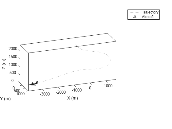
waypointTrajectory Example for Aircraft Landing
Define the trajectory of a landing aircraft using a waypointTrajectory object.
waypoints = [-421 -384 2000;
    47 -294 1600;
    1368 174 1300;
    995 1037 900;
    -285 293 600;
    -1274 84 350;
    -2328 101 150;
    -3209 83 0];
timeOfArrival =  [0; 16.71; 76.00; 121.8; 204.3; 280.31; 404.33; 624.6];
aircraftTraj = waypointTrajectory(waypoints,timeOfArrival);
Create a theaterPlot object to visualize the trajectory and the aircraft.
minCoords = min(waypoints);
maxCoords = max(waypoints);
tp = theaterPlot('XLimits',1.2*[minCoords(1) maxCoords(1)], ...
    'YLimits',1.2*[minCoords(2) maxCoords(2)], ...
    'ZLimits',1.2*[minCoords(3) maxCoords(3)]);

% Create a trajectory plotter and a platform plotter
tPlotter = trajectoryPlotter(tp,'DisplayName','Trajectory');
pPlotter = platformPlotter(tp,'DisplayName','Aircraft');
Obtain the Cartesian waypoints of the trajectory using the lookupPose object function.
sampleTimes = timeOfArrival(1):timeOfArrival(end);
numSteps = length(sampleTimes);
[positions,orientations] = lookupPose(aircraftTraj,sampleTimes);
plotTrajectory(tPlotter,{positions})
axis equal
Plot the platform motion using an airplane mesh object.
mesh = scale(rotate(tracking.scenario.airplaneMesh,[0 0 180]),15); % Exaggerated scale for better visualization
view(20.545,-20.6978)
for i = 1:numSteps
    plotPlatform(pPlotter,positions(i,:),mesh,orientations(i))
    % Uncomment the next line to slow the aircraft motion animation
    % pause(1e-7)
end
In the animation, the yaw angle of the aircraft aligns with the trajectory by default.
Create a second aircraft trajectory with the same waypoints as the first aircraft trajectory, but set its AutoPitch and AutoBank properties to true. This generates a trajectory more representative of the possible aircraft maneuvers.
aircraftTraj2 = waypointTrajectory(waypoints,timeOfArrival, ...
    'AutoPitch',true, ...
    'AutoBank',true);
Plot the second trajectory and observe the change in aircraft orientation.
[positions2,orientations2] = lookupPose(aircraftTraj2,sampleTimes);
for i = 1:numSteps
    plotPlatform(pPlotter,positions2(i,:),mesh,orientations2(i));
    % Uncomment the next line to slow the aircraft motion animation
    % pause(1e-7)
end
Visualize the orientation differences between the two trajectories in angles.
distance = dist(orientations2,orientations);
figure
plot(sampleTimes,distance*180/pi)
xlabel('Time (sec)')
ylabel('Angular Distance (deg)')
title('Orientation Difference Between Two Waypoint Trajectories')

geoTrajectory
The geoTrajectory System object generates a trajectory using
waypoints in a similar fashion as the waypointTrajectory object, but it
has two major differences in how to specify waypoints and velocity inputs.
When specifying waypoints for
geoTrajectory, express each waypoint in the geodetic coordinates of latitude, longitude, and altitude above the WG84 ellipsoid model. Using geodetic coordinates, you can conveniently specify long-range trajectories, such as airplane flight trajectory on a realistic Earth model.When specifying the orientation and velocity information for each waypoint, the reference frame for orientation and velocity is the local NED or ENU frame defined under the current trajectory waypoint. For example, the N1-E1-D1 frame shown in the figure is a local NED reference frame.

In the figure,
Ex, Ey, and Ez are the three axes of the Earth-centered Earth-fixed (ECEF) frame, which is fixed on the Earth.
(λ1, ϕ1, h1) and (λ2, ϕ2, h2) are the geodetic coordinates of the plane at the two waypoints.
(N1, E1, D1) and (N2, E2, D2) are the two local NED frames corresponding to the two trajectory waypoints.
Bx, By, and Bz are the three axes of the platform body frame, which is fixed on the platform.
geoTrajectory Example For Flight Trajectory
Load the flight data of a flight trajectory from Los Angeles to Boston. The data contains flight information including flight time, geodetic coordinates for each waypoint, course, and ground speed.
load flightData.matCreate a geoTrajectory object based on the flight data.
planeTraj = geoTrajectory([latitudes longitudes heights],timeOfArrival, ...
    'Course',courses,'GroundSpeed',speeds);
Look up the Cartesian coordinates of the waypoints in the ECEF frame.
sampleTimes = 0:1000:3600*10;
positionsCart = lookupPose(planeTraj,sampleTimes,'ECEF');
Show the trajectory using the helperGlobeView class, which approximates the Earth sphere.
viewer = helperGlobeView;
plot3(positionsCart(:,1),positionsCart(:,2),positionsCart(:,3),'r')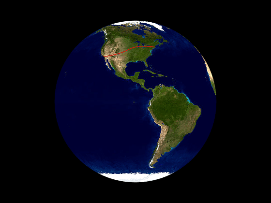
You can further explore the trajectory by querying other outputs of the trajectory.
kinematicTrajectory
Unlike the two waypoint trajectory objects, the kinematicTrajectory
System object uses kinematic attributes to specify a trajectory. Think of the
trajectory as a numerical integration of the pose (position and orientation) and linear
velocity of the platform, based on the linear acceleration and angular acceleration
information. The pose and linear velocity are specified with respected to a chosen,
fixed scenario frame, whereas the linear acceleration and angular velocity are specified
with respected to the platform body frame.
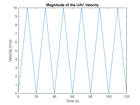
kinematicTrajectory Example For UAV Path
Create a kinematicTrajectory object for simulating a UAV path. Specify the time span of the trajectory as 120 seconds.
traj = kinematicTrajectory('SampleRate',1, ...
    'AngularVelocitySource','Property');

tStart = 0;
tFinal = 120;
tspan = tStart:tFinal;

numSteps = length(tspan);
positions = NaN(3,numSteps);
velocities = NaN(3,numSteps);
vel = NaN(1,numSteps);
To form a square path covering a small region, separate the UAV trajectory into six segments:
Taking off and ascending in the z-direction
Moving in the positive x-direction
Moving in the positive y-direction
Moving in the negative x-direction
Moving in the negative y-direction
Descending in the z-direction and landing
In each segment, the UAV accelerates in one direction and then decelerates in that direction with the same acceleration magnitude. As a result, at the end of each segment, the velocity of the UAV is zero.
segSteps = floor(numSteps/12);
accelerations = zeros(3,numSteps);
acc = 1;
% Acceleration for taking off and ascending in the z-direction
accelerations(3,1:segSteps) = acc;
accelerations(3,segSteps+1:2*segSteps) = -acc;

% Acceleration for moving in the positive x-direction
accelerations(1,2*segSteps+1:3*segSteps) = acc;
accelerations(1,3*segSteps+1:4*segSteps) = -acc;

% Acceleration for moving in the positive y-direction
accelerations(2,4*segSteps+1:5*segSteps) = acc;
accelerations(2,5*segSteps+1:6*segSteps) = -acc;

% Acceleration for moving in the negative x-direction
accelerations(1,6*segSteps+1:7*segSteps) = -acc;
accelerations(1,7*segSteps+1:8*segSteps) = acc;

% Acceleration for moving in the negative y-direction
accelerations(2,8*segSteps+1:9*segSteps) = -acc;
accelerations(2,9*segSteps+1:10*segSteps) = acc;

% Descending in the z-direction and landing
accelerations(3,10*segSteps+1:11*segSteps) =-acc;
accelerations(3,11*segSteps+1:end) = acc;
Simulate the trajectory by calling the kinematicTrajectory object with the specified acceleration.
for i = 1:numSteps
    [positions(:,i),~,velocities(:,i)] = traj(accelerations(:,i)');
     vel(i) = norm(velocities(:,i));
end
Visualize the trajectory using theaterPlot.
% Create a theaterPlot object and create plotters for the trajectory and the
% UAV Platform.
figure
tp = theaterPlot('XLimits',[-30 130],'YLimits',[-30 130],'ZLimits',[-30 130]);
tPlotter = trajectoryPlotter(tp,'DisplayName','UAV trajectory');
pPlotter = platformPlotter(tp,'DisplayName','UAV','MarkerFaceColor','g');

% Plot the trajectory.
plotTrajectory(tPlotter,{positions'})
view(-43.18,56.49)

% Use a cube to represent the UAV platform.
dims = struct('Length',10, ...
    'Width',5, ...
    'Height',3, ...
    'OriginOffset',[0 0 0]);

% Animate the UAV platform position.
for i = 1:numSteps
    plotPlatform(pPlotter,positions(:,i)',dims,eye(3))
    pause(0.01)
end

Show the velocity magnitude of the UAV platform.
figure
plot(tspan,vel)
xlabel('Time (s)')
ylabel('Velocity (m/s)')
title('Magnitude of the UAV Velocity')
kinematicTrajectory Example For Spacecraft Trajectory
Use kinematicTrajetory to specify a circular spacecraft trajectory. The orbit has these elements:
Orbital radius () — 7000 km
Inclination () — 60 degrees
Argument of ascending node () — 90 degrees. The ascending node direction is aligned with the -direction.
True anomaly () — –90 degrees
In the figure, -- is the Earth-centered inertial (ECI) frame, which has a fixed position and orientation in space. -- is the spacecraft body frame, fixed on the spacecraft. and are the initial position and velocity of the spacecraft.

To specify the circular orbit using kinematicTrajectory, you need to provide the initial position, initial velocity, and initial orientation of the spacecraft with respect to the ECI frame. For the chosen true anomaly (= –), the spacecraft velocity is aligned with the -direction.
inclination = 60; % degrees
mu = 3.986e14; % standard earth gravitational parameter
radius = 7000e3;% meters
v = sqrt(mu/radius); % speed
initialPosition = [radius*cosd(inclination),0,-radius*sind(inclination)]';
initialVelocity = [0 v 0]';
Assume the x-direction of the spacecraft body frame is the radial direction, the z-direction is the normal direction of the orbital plane, and the y-direction completes the right-hand rule. Use the assumptions to specify the orientation of the body frame at the initial position.
orientation = quaternion([0 inclination 0],'eulerd','zyx','frame');
Express the angular velocity and the angular acceleration of the trajectory in the platform body frame.
omega = v/radius;
angularVelocity = [0 0 omega]';
a = v^2/radius;
acceleration = [-a 0 0]';
Set a simulation time of one orbital period. Specify a simulation step as 2 seconds.
tFinal = 2*pi/omega;
dt = 2;
sampleRate = 1/dt;
tspan = 0:dt:tFinal;
numSteps = length(tspan);
Create the spacecraft trajectory. Since the acceleration and angular velocity of the spacecraft remain constant with respect to the spacecraft body frame, specify them as constants. Generate position and orientation outputs along the trajectory by using the kinematicTrajectory object.
traj = kinematicTrajectory('SampleRate',sampleRate, ...
    'Position',initialPosition, ...
    'Velocity',initialVelocity, ...
    'Orientation',orientation, ...
    'AngularVelocity',angularVelocity, ...
    'Acceleration',acceleration, ...
    'AccelerationSource','Property', ...
    'AngularVelocitySource','Property');

% Generate position and orientation outputs.
positions = NaN(3,numSteps);
orientations = zeros(numSteps,1,'quaternion');
for i = 1:numSteps
   [positions(:,i),orientations(i)] = traj();
end
Use the helperGlobeView class and theaterPlot to show the trajectory.
viewer = helperGlobeView(0,[60 0]);
tp = theaterPlot('Parent',gca,...
    'XLimits',1.2*[-radius radius],...
    'YLimits',1.2*[-radius radius],...
    'ZLimits',1.2*[-radius radius]);
tPlotter = trajectoryPlotter(tp,'LineWidth',2);
pPlotter = platformPlotter(tp,'MarkerFaceColor','m');
legend(gca,'off')

plotTrajectory(tPlotter,{positions'})
% Use a cube with exaggerated dimensions to represent the spacecraft.
dims = struct('Length',8e5,'Width',4e5,'Height',2e5,'OriginOffset',[0 0 0]);

for i = 1:numSteps
   plotPlatform(pPlotter,positions(:,i)',dims,orientations(i))
   % Since the reference frame is the ECI frame, earth rotates with respect to it.
   rotate(viewer,dt)
end

Summary
In this topic, you learned how to use three trajectory objects to customize your own trajectories based on the available information. In addition, you learned the fundamental differences in applying them. This table highlights the main attributes of these trajectory objects.
| Trajectory Object | Position Inputs | Linear Velocity Inputs | Orientation | Acceleration and Angular Velocity Inputs | Recommended Distance Span |
|---|---|---|---|---|---|
waypointTrajectory | Cartesian waypoints expressed in a fixed frame (NED or ENU) | One of these options:
| One of these options:
| Cannot specify | From within tens to hundreds of kilometers |
geoTrajectory
| Geodetic waypoints in the ECEF frame | One of these options:
| One of these options:
| Cannot specify | From hundreds to thousands of kilometers |
kinematicTrajectory | Initial position expressed in a chosen, fixed frame | Only initial velocity in the fixed frame | Only initial orientation in the fixed frame | Specify acceleration and angular velocity in the platform body frame | Unlimited distance span |