EDSADC Peripheral Configuration
Map EDSADC peripherals in Infineon AURIX model to peripheral registers in MCU
Since R2024b
Description
Add-On Required: This feature requires the Embedded Coder Support Package for Infineon AURIX TC3x Microcontrollers add-on.
View and edit the map of peripherals in the Infineon® AURIX™ model to the hardware peripherals.
Using the Hardware Mapping tool, you can:
View and edit configuration parameters of the EDSADC block.
Check for conflicts, if any, between peripherals.

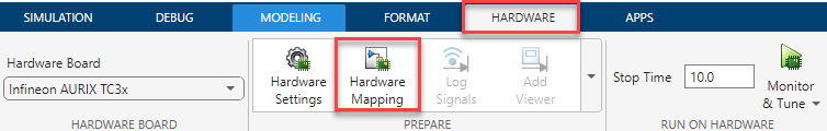
Open the EDSADC Peripheral Configuration
In the Hardware tab, click Hardware Mapping.
Parameters
Global Parameters > Model Configuration
Specify the voltage configuration of the EDSADC module.
Specify the dithering intensity (white noise).
Channel
Select the type of modulator that the EDSADC module utilizes for delta-sigma conversion.
Select the reference voltage that determines the total voltage range that the ADC can convert into a digital value without saturating.
Maximum count for full-scale voltage.
Note
When you configure for an unsigned datatype, the result will be a signed conversion + 32767. For example, for 3.3V, the converted value for signed operation is 3.3/5*25000=16500 and for unsigned datatype, the value is 16500+32767=49267.
Channel > Common mode voltage configuration
Disable or specify the fractional reference voltage for delta-sigma conversion.
Dependencies
To enable this parameter, set the Modulator type
parameter to on-chip.
Channel > Modulator
Specify the clock source for the external modulator.
Dependencies
To enable this parameter, set the Modulator type
parameter to External.
Specify clock frequency for the external and on-chip modulators.
Specify the pin number for the data signal.
Dependencies
To enable this parameter, set the Modulator type
parameter to External.
Specify pin number for clock signal.
Note
If you set Clock source to
External, the modulator clock pin inputs the clock signal generated by the external modulator.If you set Clock source to
Internal, the modulator clock pin outputs the internally generated clock signal, which can be used by external modulator.
Dependencies
To enable this parameter, set the Modulator type
parameter to External.
Specify the type of trigger edge to capture data.
Dependencies
To enable this parameter, set the Modulator type
parameter to External.
Specify gain factor for the external modulator.
Dependencies
To enable this parameter, set the Modulator type
parameter to External.
Specify the clock sync delay for the on-chip modulator.
Dependencies
To enable this parameter, set the Modulator type
parameter to On-chip.
Specify the type of positive input for delta-sigma conversion.
Note
The EDSADC module supports differential inputs where you can configure both positive and negative inputs accordingly. In case of single-ended applications, you can configure the unused pin with ground.
Dependencies
To enable this parameter, set the Modulator type
parameter to On-chip.
Specify the pin number for the positive input.
Dependencies
To enable this parameter, set the Modulator type
parameter to On-chip and Positive input
type parameter to Input-pin.
Specify the type of negative input for delta-sigma conversion.
Dependencies
To enable this parameter, set the Modulator type
parameter to On-chip.
Specify the pin number of the negative input.
Dependencies
To enable this parameter, set the Modulator type
parameter to On-chip and Negative input
type parameter to Input-pin.
Channel > Pin configuration
Select the configuration mode of EDSADC input pin.
Select the pin speed for EDSADC.
Select the voltage level for the EDSADC pin.
Add dithering (white noise) at the intensity level specified in the Dithering levels parameter.
Dependencies
To enable this parameter, set the Modulator type
parameter to On-chip.
Select to enable auto-calibration, if required.
Dependencies
To enable this parameter, set the Modulator type
parameter to On-chip.
Channel > Trigger configuration
Specify the hardware trigger source for the EDSADC channel. The trigger signals options vary based on the choice of Timer unit and Channel # parameters in PWM Peripheral Configuration tool.
For more information on EDSADC trigger signals, see EDSADC Trigger Signals.
Timestamp
Specify the frequency of timestamp measurement.
Dependencies
This parameter appears only if you select the Enable timestamp parameter in the EDSADC block in the Simulink® model.
Specify the hardware trigger edge for the timestamp measurement.
Dependencies
This parameter appears only if you select the Enable timestamp parameter in the EDSADC block in the Simulink model.
Filter
Select to enable a pre-filter to reduce the data rate for modular frequencies above 20 MHz. This pre-filter is a CIC filter with the fixed decimation rate of 2.
Filter > CIC filter configuration
Decimation factor for the EDSADC conversion. A higher value improves accuracy at the cost of additional time.
Specify the start value of the CIC filter.
Filter > Overshoot
Select to enable an overshoot compensation filter before passing the CIC filter result to FIR filters.
Filter > FIR Filter
Select to enable or bypass the FIR0 filter. The FIR0 filter attenuates the high frequency components that passed the CIC filter.
Select to enable an FIR1 filter with decimation options.
Filter > Ripple compensation
Select to enable ripple compensation to attenuate low-frequency noise.
Filter > Offset Filter
Specify offset compensation for EDSADC conversion.
Integrator
Select to enable the integrator module for EDSADC conversion.
Select to enable trigger control to start the integrator module.
Dependencies
To enable this parameter, select the Enable integrator parameter.
Specify the hardware trigger edge to start integration window.
Dependencies
To enable this parameter, select the Enable integrator and Enable external trigger control to start integrator parameters.
Specify the number of values to discard during integration.
Dependencies
To enable this parameter, select the Enable integrator parameter.
Specify the number of values to consider for accumulation during integration.
Dependencies
To enable this parameter, select the Enable integrator parameter.
Select to restart filter chain results when integration window starts.
Dependencies
To enable this parameter, select the Enable integrator parameter.
Select to enable external trigger to control start and stop of integration window.
Dependencies
To enable this parameter, select the Enable integrator parameter.
Specify the number of integration cycles.
Dependencies
To enable this parameter, select the Enable integrator, Enable external trigger control to start integratorparameters and disable the Enable external trigger control to stop integrator parameter.
Filter > Auxiliary filter chain configuration
Specify the decimation factor of the auxiliary CIC filter.
Dependencies
This parameter appears only if you select the Auxiliary result parameter in the EDSADC block in the Simulink model.
Boundary
Lower limit for the boundary band for checking the result.
Upper limit for the boundary band for checking the result.
Boundary condition for the auxiliary interrupt.
Events
Select to enable an interrupt for the main filter.
Select one of these options as the interrupt condition for the main filter. To
limit conversion interrupts, select High or
Low.
Dependencies
To enable this parameter, select the Enable main event parameter.
Select to enable the auxiliary interrupt.
Select the type of auxiliary interrupt. You can view the Timestamp
event option if you select the Enable
timestamp parameter in the EDSADC block in the Simulink model.
If you enable the Auxiliary result parameter in the EDSADC block and set Interrupt type to
Boundary event, then the boundary conditions set in Boundary tab apply to the auxiliary filter result.If you disable the Auxiliary result parameter in the EDSADC block and set Interrupt type to
Boundary event, then the boundary conditions set in Boundary tab apply to the main filter result.
Version History
Introduced in R2024b
MATLAB Command
You clicked a link that corresponds to this MATLAB command:
Run the command by entering it in the MATLAB Command Window. Web browsers do not support MATLAB commands.
Web サイトの選択
Web サイトを選択すると、翻訳されたコンテンツにアクセスし、地域のイベントやサービスを確認できます。現在の位置情報に基づき、次のサイトの選択を推奨します:
また、以下のリストから Web サイトを選択することもできます。
最適なサイトパフォーマンスの取得方法
中国のサイト (中国語または英語) を選択することで、最適なサイトパフォーマンスが得られます。その他の国の MathWorks のサイトは、お客様の地域からのアクセスが最適化されていません。
南北アメリカ
- América Latina (Español)
- Canada (English)
- United States (English)
ヨーロッパ
- Belgium (English)
- Denmark (English)
- Deutschland (Deutsch)
- España (Español)
- Finland (English)
- France (Français)
- Ireland (English)
- Italia (Italiano)
- Luxembourg (English)
- Netherlands (English)
- Norway (English)
- Österreich (Deutsch)
- Portugal (English)
- Sweden (English)
- Switzerland
- United Kingdom (English)