Main Content

Analog Output

Output data to multiple analog channels of data acquisition device

  • Analog_Output block

Libraries:
Data Acquisition Toolbox

Description

The Analog Output block opens, initializes, configures, and controls an analog data acquisition device. The opening, initialization, and configuration of the device occur once at the start of the model execution. During the model run time, the block outputs data to the hardware synchronously (outputs the block of data as it is provided). On every time step, the block performs a blocking synchronous write to the hardware, outputting the entire input data.

The following diagram shows the timing of the synchronous analog output.
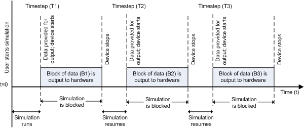
Timing of synchronous analog output

At the first time step (T1), data output is initiated and the corresponding block of data (B1) is output to the hardware. The simulation does not continue until B1 is output completely.

The block has one or more input ports, depending on the option you choose in its parameters dialog box. It has no output ports.

The Analog Output block inherits the sample time from the driving block connected to the input port. The valid data types of the signal at the input port are double or native data types supported by the hardware.

Notes

To use this block, you need both Data Acquisition Toolbox™ and Simulink® software.

You can use the Analog Output block only with devices that support clocked generation. To generate data using devices that do not support clocking, use the Analog Output (Single Sample) block.

Some devices are not supported by the Simulink blocks in Data Acquisition Toolbox. To see if your device supports Simulink, refer to Supported Hardware.

Other Supported Features

  • This block supports the use of text accelerator mode, but not Rapid Accelerator or code generation.

  • The block supports the use of model referencing, so that your model can include other Simulink models as modular components.

For more information on these features, see the Simulink documentation.

Examples

Ports

Input

expand all

Analog output to generate, specified as doubles. If using only one input port for all channels, specify an M-by-N matrix for a blocksize of M scans on N channels. Each scan is a row across N channels. Each channel outputs a column of M scans.

If using a port for each channel, specify a column of data for each channel on each port. Multiple ports are named by channel names or device specified channel IDs.

Data Types: double

Parameters

expand all

The device from which you want to generate data. The items in the list vary, depending on which devices you have connected to your system. Devices in the list are specified by adaptor/vendor name and unique device ID, followed by the model name of the device, for example, ni Dev1 (USB-6255). The first available device is selected by default. A CompactDAQ chassis is shown as a single device; vendor name, chassis ID, and chassis model would be shown in the list, for example, ni cDAQ2 (cDAQ-9172).

Device channel selection and configuration table. The channel configuration table lists the hardware channels of your device, and lets you select and configure them. Specify which channels to acquire data from (by default all the channels are selected). The following parameters are specified for each selected channel:

Channel ID — Hardware channel ID specified by the device. The Channel ID column is read-only, and the parameters are defined when the device is selected.

Name — Channel name. By default the table displays any names provided by the hardware, but you can edit the names. For example, if the device is a sound card with two channels, you can name them Left and Right.

Module — Device ID the channel belongs to. The Module column is read-only. If a CompactDAQ chassis is selected, it shows the ID of the CompactDAQ module which the channel belongs to; otherwise the ID of the device.

Measurement Type — Measurement type of the channel. This block supports only voltage measurement types. (For other measurement types, use a DataAcquisition object in MATLAB®.)

Output Range — Output ranges available for each channel supported by the hardware, defined when a device is selected.

Number of input data ports, specified as:

1 for all channels (default) — One input port on the block for all channels. Provide data as a matrix, with a size of scan blocksize by number of channels, M-by-N.

1 per channel — N input ports on the block, where N is equal to the number of selected channels. Provide each port data as a column vector with a size of blocksize-by-1. For naming, each output port uses the channel name if one was specified, otherwise the channel ID, for example, ao1.

The rate at which samples are output from Simulink to the device, in samples per second. This is the sampling rate for the hardware. The default is defined when a device is selected. The sample rate must be a positive real number within the range allowed for the selected hardware.

Version History

Introduced in R2016b