Starter
Starter as a DC motor
Libraries:
Powertrain Blockset /
Energy Storage and Auxiliary Drive /
Starter
Description
The Starter block implements a starter assembly as a separately excited DC motor, permanent magnet DC motor, or series connection DC motor. The motor operates as a torque source to an internal combustion engine.
Use the Starter block:
In an engine model with a front-end accessory drive (FEAD)
To model engine start and stop scenarios
The Starter block supports only an angular speed input to the DC motor. A load torque input requires engine dynamics.
Separately Excited DC
                        Motor
In a separately excited DC motor, the field winding is connected to a separate source of DC power.
The relationship between the field winding voltage, field resistance, and field inductance is given by:
The counter-electromotive force is a product of the field resistance, mutual inductance, and motor shaft angular speed:
The armature voltage is given by:
The starter motor current load is the sum of the field winding current and armature winding current:
The starter motor shaft torque is the product of the armature current, field current, and mutual inductance:
Permanent Magnet DC Motor
In a permanent magnet DC motor, the magnets establish the excitation flux, so there is no field current.
The counter-electromotive force is proportional to the motor shaft angular speed:
The armature voltage is given by:
The starter motor current load is equal to the armature winding current:
The starter motor shaft torque is proportional to the armature winding current:
Series Excited DC
                                Motor
A series excited DC motor connects the armature and field windings in series with a common DC power source.
The counter-electromotive force is a product of the field and armature initial series current, field, and armature mutual inductance and motor shaft angular speed:
The field and armature winding voltage is given by:
The starter motor current load is equal to the field and armature series current:
The starter motor shaft torque is the product of the squared field and armature series current and the field and armature mutual inductance:
For motor stability, the motor shaft angular speed must be greater than the ratio of the series connected field and armature resistance to the mutual inductance:
Power Accounting
For the power accounting, the block implements these equations.
| Bus Signal | Description | Variable | Equations | ||
|---|---|---|---|---|---|
|
|
| Mechanical power | Pmot | |
PwrBus | Electrical power | Pbus | Separately excited DC motor | ||
PM excited DC motor | |||||
Series excited DC motor | |||||
|
| PwrLoss | Motor losses | Ploss | ||
|
| PwrInd | Electrical inductance | Pind | Separately excited DC motor | |
PM excited DC motor | |||||
Series excited DC motor | |||||
The equations use these variables.
| Ra | Armature winding resistance |
| La | Armature winding inductance |
| EMF | Counter-electromotive force |
| Rf | Field winding resistance |
| Lf | Field winding inductance |
| Laf | Field and armature mutual inductance |
| ia | Armature winding current |
| if | Field winding current |
| Kt | Motor torque constant |
| ω | Motor shaft angular speed |
Va | Armature winding voltage |
Vf | Field winding voltage |
Vaf | Field and armature winding voltage |
| iaf | Field and armature series current |
| Rser | Series connected field and armature resistance |
| Lser | Series connected field and armature inductance |
iload | Starter motor current load |
Tmech | Starter motor shaft torque |
Examples
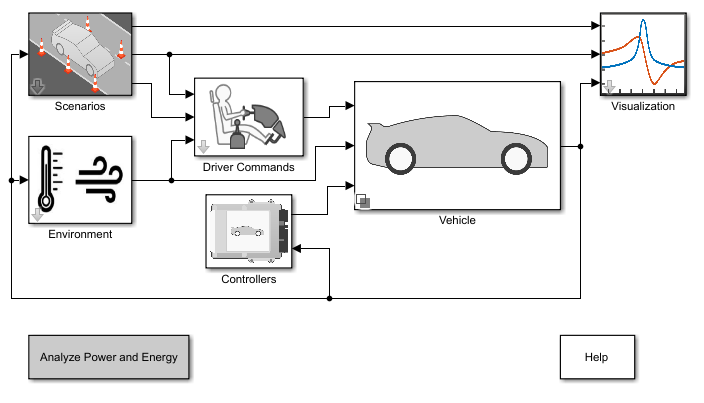
Build Conventional Vehicle Model
Build a vehicle with an internal combustion engine using the conventional vehicle reference application.
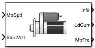
Ports
Inputs
Output
Parameters
References
[1] Krause, P. C. Analysis of Electric Machinery. New York: McGraw-Hill, 1994.
Extended Capabilities
Version History
Introduced in R2017a