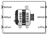
Reduced Lundell Alternator
Reduced Lundell (claw-pole) alternator with an external voltage regulator
Libraries:
Powertrain Blockset /
Energy Storage and Auxiliary Drive /
Alternator
Description
The Reduced Lundell Alternator block implements a reduced Lundell (claw-pole) alternator with an external voltage regulator. The back-electromotive force (EMF) voltage is proportional to the input velocity and field current. The motor operates as a source torque to the internal combustion engine.
Use the Reduced Lundell Alternator block:
To model an automotive electrical system
In an engine model with a front-end accessory drive (FEAD)
The calculated motor shaft torque is in the opposite direction of the engine speed. You can:
Tune the external voltage regulator to a desired bandwidth. The stator current and two diode drops reduce the stator voltage.
Filter the load current to desired bandwidth. The load current has a lower saturation of 0 A.
The Reduced Lundell Alternator block implements equations for the electrical, control, and mechanical systems that use these variables.
Electrical
To calculate voltages, the block uses these equations.
| Calculation | Equations |
|---|---|
| Alternator output voltage | |
| Field winding voltage |
Control
The controller assumes no resistance or voltage drop.
| Calculation | Equations |
|---|---|
Field winding voltage transform | |
Field winding current transform | |
Open loop electrical transfer function | |
Open loop voltage regulator transfer function | |
Closed loop transfer function | |
Closed loop controller design |
Mechanical
To calculate torques, the block uses these equations.
| Calculation | Equations |
|---|---|
| Electrical torque | |
| Frictional torque | |
| Windage torque | |
| Torque at start | when |
| Motor shaft torque |
Power Accounting
For the power accounting, the block implements these equations.
| Bus Signal | Description | Variable | Equations | ||
|---|---|---|---|---|---|
|
|
| Mechanical power | Pmot | |
PwrBus | Electrical power | Pbus | |||
|
| PwrLoss | Motor power loss | Ploss | ||
|
| PwrInd | Electrical winding loss | Pind | ||
The equations use these variables.
vref | Alternator output voltage command |
vf | Field winding voltage |
if | Field winding current |
is | Stator winding current |
Vd | Diode voltage drop |
Rf | Field winding resistance |
Rs | Stator winding resistance |
Lf | Field winding inductance |
Kv | Voltage constant |
Fv | Voltage regulator bandwidth |
Fc | Input current filter bandwidth |
Vfmax | Field control voltage upper saturation limit |
Vfmin | Field control voltage lower saturation limit |
Kc | Coulomb friction coefficient |
Kb | Viscous friction coefficient |
Kw | Windage coefficient |
ω | Motor shaft angular speed |
iload | Alternator load current |
vs | Alternator output voltage |
τmech, Tmech | Motor shaft torque |
Examples
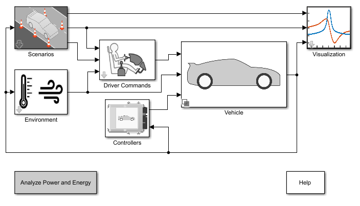
Build Conventional Vehicle Model
Build a vehicle with an internal combustion engine using the conventional vehicle reference application.
Ports
Inputs
Output
Parameters
References
[1] Krause, P. C. Analysis of Electric Machinery. New York: McGraw-Hill, 1994.
Extended Capabilities
Version History
Introduced in R2017a