Hardware Connections
Connect F280049C LaunchPad to BOOSTXL-POSMGR
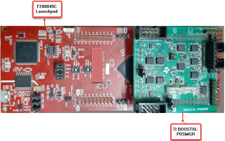
Mount the TI BOOSTXL-POSMGR on top of F280049C LaunchPad as shown in the following figure.

Ensure the following pin map connections are made between the Texas Instruments® Piccolo F280049C LaunchPad and Texas Instruments BOOSTXL-POSMGR.
Pin Mapping
| BOOSTXL-POSMGR | Launchpad-F280049c | Description |
|---|---|---|
| J4 [pin 2] Enc1-CLK | J8 [pin 80] (ePWM1A) | BiSS-C clock from controller to encoder |
| J4 [pin 4] eQEP1B | J8 [pin 79] (ePWM1B) | SPI clock generated from MCU |
| J1 [pin 14] SPI-1-CLK | J5 [pin 47] (SPIB_CLK) | One SPI instance to emulate the BISS-C interface (SPIB on Launchpad) |
| J2 [pin 11] Enc1-DI | J6 [pin 55] (SPIB_MOSI) | |
| J2 [pin 13] Enc1-DO | J6 [pin 54] (SPIB_MISO) | |
| J2 [pin 3] SPISTE | J6 [pin 59] (SPIB_STE) | |
| J1 [pin 6] PWREN1 | J5 [pin 43] (GPIO28_BP) | Encoder power enable |
Connect BOOSTXL-POSMGR to Absolute Encoder
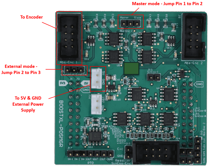
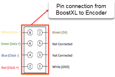
Connect the Texas Instruments BOOSTXL-POSMGR to Absolute Encoder as detailed in the following figure.

To Encoder - Use female to female hookup wires to wire the encoder to the header as shown in the following figure. The colors correspond to the encoder wires that are soldered to the connector.

5V External Power Supply - Connect 5V and GND to the external power supply. Use 2 banana clip to mini grabber wires. Use 2 male to female hookup wires to connect from mini grabbers to the external 5V and GND.
controller mode - Use female to female hookup wire to jump pin 1 to pin 2 which sets the booster pack to controller mode.
External power mode - Use female to female hookup wire to jump pin 2 to pin 3 which sets the booster pack to external power mode.
Encoder Connections
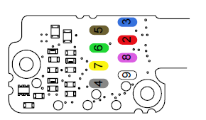
Ensure the following wire connections are mapped to the absolute shaft encoder (BiSS).
Encoder Electrical Connection
| Pin / Pad | Wire Color | BiSS |
| Housing | Outer shield | Encoder/machine case (Earth connection) |
| 1 | Inner shield | 0 V (GND) |
| 2 | Red | MA+ |
| 3 | Blue | MA– |
| 4 | Grey | - |
| 5 | Brown | 5 V supply |
| 6 | Green | SLO+ |
| 7 | Yellow | SLO– |
| 8 | Pink | - |
| 9 | White | 0 V (GND) |
