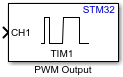
PWM Output
Libraries:
STM32 Microcontroller Blockset /
STM32F1xx Based Boards
STM32 Microcontroller Blockset /
STM32F2xx Based Boards
STM32 Microcontroller Blockset /
STM32F3xx Based Boards
STM32 Microcontroller Blockset /
STM32F4xx Based Boards
STM32 Microcontroller Blockset /
STM32F7xx Based Boards
STM32 Microcontroller Blockset /
STM32G0xx Based Boards
STM32 Microcontroller Blockset /
STM32G4xx Based Boards
STM32 Microcontroller Blockset /
STM32H5xx Based Boards
STM32 Microcontroller Blockset /
STM32H7xx Based Boards
STM32 Microcontroller Blockset /
STM32L4xx Based Boards
STM32 Microcontroller Blockset /
STM32L5xx Based Boards
STM32 Microcontroller Blockset /
STM32U5xx Based Boards
STM32 Microcontroller Blockset /
(Legacy) STM32 MBED Based Boards /
STM32F746G-Discovery
STM32 Microcontroller Blockset /
(Legacy) STM32 MBED Based Boards /
STM32L475VG-Discovery (B-L475E-IOT01A)
STM32 Microcontroller Blockset /
(Legacy) STM32 MBED Based Boards /
STM32F769I-Discovery
STM32 Microcontroller Blockset /
STM32WBxx Based Boards
Description
Use the PWM Output block to generate a square waveform on the enabled channels using the timer module.
The block input controls the duty cycle of the square waveform for each channel.
If you set Duty Cycle unit parameter to
Percentage, an input value of 0 produces a 0 percent duty
cycle and an input of 100 produces an output with 100 percent duty cycle on the
corresponding channel. If you set the Duty Cycle unit parameter to
Counts, the block writes input value to the capture
compare register of the corresponding channel.
If you select the Enable frequency input, the block writes the corresponding input to the autoreload register of the timer to set the counter period.
Note
You can run a Simulink® model containing PWM Output block in Connected IO mode on STM32 Processor Based Boards. For more information, see Communicate with Hardware Using Connected IO.
Examples
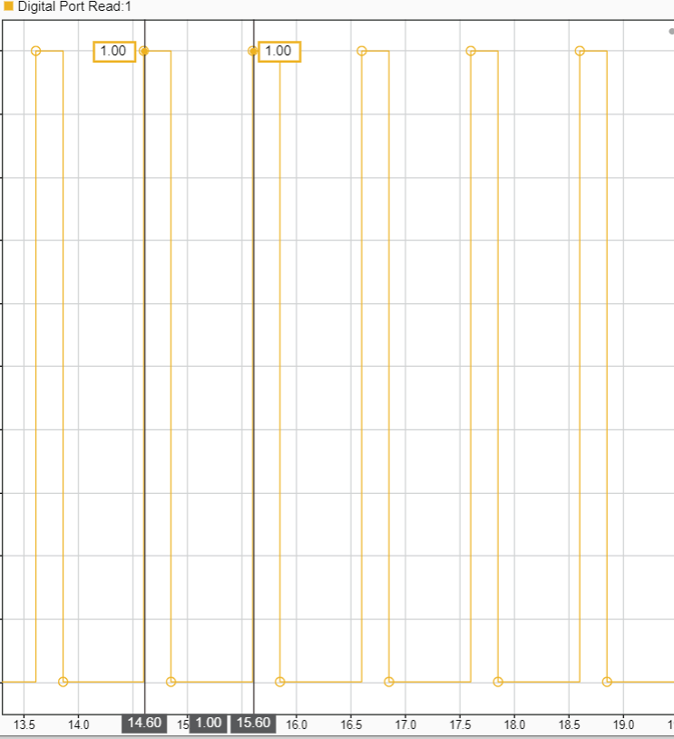
Signal Monitoring and Parameter Tuning of Generated PWM Output
Generate PWM signals on an STM32 processor-based board and tune parameters in real time using External mode.
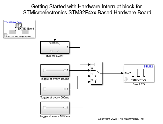
Using Hardware Interrupt Block to Create an ISR on STMicroelectronics STM32 Processor Based Boards
Use a Hardware Interrupt block to create an interrupt service routine (ISR) in the generated code for STM32™ Microcontroller Blockset.
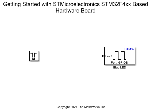
Get Started with STMicroelectronics STM32 Processor Based Boards
Run a Simulink model on STM32 processor.
Ports
Input
The input port considers the duty cycle of the corresponding channel.
If you set the Duty cycle units parameter to
Percentage, specify a value range between
0 to 100. If you set the duty
cycle unit to Counts, specify a value range for 32
bit timers between 0 to 0xFFFFFFFF
and for 16 bit timers between 0 to
0xFFFF.
Dependencies
To enable this port, select the Enable channel parameter.
Data Types: Boolean | uint16 | uint32 | int8 | uint8 | int16 | int32 | uint64 | int64 | single | double
The input port considers capture/compare enable input of the corresponding channel.
Dependencies
To enable this port, select the Enable Capture/Compare Enable (CC#E) input parameter.
Data Types: Boolean | uint16 | uint32 | int8 | uint8 | int16 | int32 | uint64 | int64 | single | double
The input port considers capture/compare complementary enable input of the corresponding channel.
Dependencies
To enable this port, select the Enable Capture/Compare Complementary Enable (CC#NE) input parameter.
Data Types: Boolean | uint16 | uint32 | int8 | uint8 | int16 | int32 | uint64 | int64 | single | double
The input port considers output compare mode input of the corresponding channel.
Dependencies
To enable this port, select the Enable Output Compare Mode (OC#M) input parameter.
Data Types: Boolean | uint16 | uint32 | int8 | uint8 | int16 | int32 | uint64 | int64 | single | double
Use this port to enable input port counter. Set the port to one of these values.
0- Disable counter1- Enable counter
Dependencies
To enable this port, select the Enable input to enable/disable timer parameter.
Data Types: Boolean | uint16 | uint32 | int8 | uint8 | int16 | int32 | uint64 | int64 | single | double
This main output enable (MOE) bit is cleared asynchronously by the hardware as soon as the break input is active.
If input is 1, then the MOE bit is set as
1.
Dependencies
To enable this port, select the Enable main output enable (MOE) input parameter.
Data Types: Boolean | uint16 | uint32 | int8 | uint8 | int16 | int32 | uint64 | int64 | single | double
The input at this port determines the frequency of the counter. This value is written directly to the auto reload register.
The frequency count for 32 bit timers is between 0
to 0xFFFFFFFF and for 16 bit timers is between
0 to 0xFFFF.
Dependencies
To enable this port, select the Enable frequency input parameter.
Data Types: Boolean | uint16 | uint32 | int8 | uint8 | int16 | int32 | uint64 | int64 | single | double
Use this port to generate an update event. When you specify a value of
1, the port generates an update event.
Dependencies
To enable this port, select the Enable update generation event input parameter.
Data Types: Boolean | uint16 | uint32 | int8 | uint8 | int16 | int32 | uint64 | int64 | single | double
Use this port to generate capture compare generation event. When you
specify a value of 1, the port generates an capture
compare event.
Dependencies
To enable this port, select the Enable capture compare # generation event input parameter.
Data Types: Boolean | uint16 | uint32 | int8 | uint8 | int16 | int32 | uint64 | int64 | single | double
Use this port to generate trigger event. When you specify a value of
1, the port generates an trigger event.
Dependencies
To enable this port, select the Enable trigger generation event input parameter.
Data Types: Boolean | uint16 | uint32 | int8 | uint8 | int16 | int32 | uint64 | int64 | single | double
Use this port to generate break generation event. When you specify a
value of 1, the port generates an break generation
event.
Dependencies
To enable this port, select the Enable break generation event input parameter.
Data Types: Boolean | uint16 | uint32 | int8 | uint8 | int16 | int32 | uint64 | int64 | single | double
Use this port to generate break 2 generation event. When you specify a
value of 1, the port generates an break 2 generation
event and MOE status is cleared.
Dependencies
To enable this port, select the Enable break generation 2 event input parameter.
Data Types: Boolean | uint16 | uint32 | int8 | uint8 | int16 | int32 | uint64 | int64 | single | double
Output
The block outputs the current direction of the counter as one of the following:
0 - Up counter
1 - Down counter
Dependencies
To enable this port, select the Enable timer counter direction output parameter.
Data Types: Boolean
Status of the main output enable (MOE) bit.
Dependencies
To enable this port, select the Enable main output enable (MOE) status output parameter.
Data Types: Boolean
The simulation-only message output port, when connected to an PWM Interface (SoC Blockset) block, acts as pass-through with the output emitted on the output of the PWM Interface block during simulation.
Note
The PWM Interface (SoC Blockset) does not use the frequency input of this block and must be set manually in the PWM Interface block mask.
For STM32F7xx, STM32H7xx, and STM32G4xx based boards, channel 5 and channel 6 are not supported for simulation. However, code generation is supported for all channels.
Dependencies
To enable this port, select the Enable simulation port parameter.
Data Types: SoCData
Parameters
Main
Select the timer module. Number of timer module available will vary for different processors.
Note
Ensure that Timer module is also configured
in the STM32CubeMX project.
Programmatic Use
Block Parameter:
TimerModule |
The block input controls the duty cycle of the square waveform for each channel.
If Duty Cycle unit is
Percentage, an input value of 0 produces
a 0 percent duty cycle and an input of 100 produces a 100 percent duty
cycle output on the corresponding channel. If Duty Cycle
unit is Counts, the input
value is written to the Capture Compare register of the corresponding
channel.
Programmatic Use
Block Parameter:
DutycycleUnits |
Enable the channels on which you want the block to generate the PWM output. The input considers the duty cycle of the corresponding channels.
Each Timer module can have one to six channels. Number of channels available vary based on the timer module selected. Enable the channel supported for the corresponding timer. By default, the block enables channel 1.
Note
Ensure that the channels you want to enable are configured for PWM generation in the STM32CubeMX project.
Dependencies
The number of channels available depends on the module you select in the Timer module parameter.
Programmatic Use
Block Parameter:
EnableChannel1 |
EnableChannel2 |
EnableChannel3 |
EnableChannel4 |
EnableChannel5 |
EnableChannel6 |
Enable this parameter to generate a capture/compare input through the input port.
Dependencies
To enable this parameter, select the corresponding Enable channel# parameter.
Programmatic Use
Block Parameter:
EnableCaptureCompare1Input |
EnableCaptureCompare2Input |
EnableCaptureCompare31Input |
EnableCaptureCompare4Input |
EnableCaptureCompare5Input |
EnableCaptureCompare6Input |
Enable this parameter to generate a capture/compare complementary input through the input port.
Dependencies
To enable this parameter, select the corresponding Enable channel# parameter.
Programmatic Use
Block Parameter:
EnableCaptureCompare1ComplementaryInput |
EnableCaptureCompare2ComplementaryInput |
EnableCaptureCompare3ComplementaryInput |
EnableCaptureCompare4ComplementaryInput |
Enable this parameter to generate a output compare mode input through the input port.
Dependencies
To enable this parameter, select the corresponding Enable channel# parameter.
Programmatic Use
Block Parameter:
EnableOutputCompare1ModeInput |
EnableOutputCompare2ModeInput |
EnableOutputCompare3ModeInput |
EnableOutputCompare4ModeInput |
EnableOutputCompare5ModeInput |
EnableOutputCompare6ModeInput |
Enable or disable the counter through the input port. If you do not select this parameter, then the counter is enabled during model initialization.
Programmatic Use
Block Parameter:
EnableCounterInput |
Enable this parameter to set the main output enable (MOE) bit to recover from a break.
Dependencies
To enable this parameter, set the Timer
module parameter to either TIM1 or
TIM8.
Programmatic Use
Block Parameter:
EnableMainOutputInput |
Enable this parameter to set the frequency of the timer. All the channel outputs have the same frequency.
Programmatic Use
Block Parameter:
EnableFrequencyInput |
For odd values in the repetition counter, the update event occurs on underflow or overflow depending on when you set the repetition counter.
By default, the block sets repetition counter before you enable the timer counter, so an update event occurs on underflow.
If you enable this parameter, the block sets repetition counter after you enable the time counter, so an update events occur on overflow.
Dependencies
To enable this parameter, set the Timer
module parameter to either TIM1 or
TIM8.
Programmatic Use
Block Parameter:
SetRCAfterCE |
Enable this parameter to output the current direction of the counter.
Programmatic Use
Block Parameter:
OutputDirection |
Enable this parameter to output the main output enable (MOE) bit status.
Dependencies
To enable this parameter, set the Timer
module parameter to either TIM1 or
TIM8.
Programmatic Use
Block Parameter:
OutputMainOutputEnableStatus |
Select this parameter to add an SoC Blockset compatible simulation output port.
Programmatic Use
Block Parameter:
EnableSimPort |
Events
Enable this parameter to generate an update event through input port.
Programmatic Use
Block Parameter:
EnableUpdateEvent |
Enable this parameter to generate a capture compare event through the input port.
Dependencies
The number of Enable capture compare # generation event input parameters available depends on the module you select in the Timer module.
Programmatic Use
Block Parameter:
EnableCaptureCompare1Event |
EnableCaptureCompare2Event |
EnableCaptureCompare3Event |
EnableCaptureCompare4Event |
Enable this parameter to generate a trigger event through the input port.
Programmatic Use
Block Parameter:
EnableTriggerEvent |
Enable this parameter to generate a break event through the input port.
Dependencies
To enable this parameter, set the Timer
module parameter to either TIM1,
TIM8, TIM15,
TIM16, TIM17 or
TIM20.
Programmatic Use
Block Parameter:
EnableBreakEvent |
Enable this parameter to generate a break 2 event through the input port.
Dependencies
To enable this parameter, set the Timer
module parameter to either TIM1,
TIM8 or TIM20.
Programmatic Use
Block Parameter:
EnableBreakEvent2 |
Specify how often (in seconds) the status of enabled output ports are read if no input ports are selected. Enter a value greater than zero. When you specify this parameter as -1, Simulink determines the best sample time for the block based on the block context within the model.
Dependencies
To enable the Sample time parameter, deselect all the input ports.
Programmatic Use
Block Parameter:
SampleTime |
Version History
Introduced in R2021b
MATLAB Command
You clicked a link that corresponds to this MATLAB command:
Run the command by entering it in the MATLAB Command Window. Web browsers do not support MATLAB commands.
Web サイトの選択
Web サイトを選択すると、翻訳されたコンテンツにアクセスし、地域のイベントやサービスを確認できます。現在の位置情報に基づき、次のサイトの選択を推奨します:
また、以下のリストから Web サイトを選択することもできます。
最適なサイトパフォーマンスの取得方法
中国のサイト (中国語または英語) を選択することで、最適なサイトパフォーマンスが得られます。その他の国の MathWorks のサイトは、お客様の地域からのアクセスが最適化されていません。
南北アメリカ
- América Latina (Español)
- Canada (English)
- United States (English)
ヨーロッパ
- Belgium (English)
- Denmark (English)
- Deutschland (Deutsch)
- España (Español)
- Finland (English)
- France (Français)
- Ireland (English)
- Italia (Italiano)
- Luxembourg (English)
- Netherlands (English)
- Norway (English)
- Österreich (Deutsch)
- Portugal (English)
- Sweden (English)
- Switzerland
- United Kingdom (English)


