Schedule Operations in a Hydraulic Control System
This example shows how to implement mode-based execution and event-driven scheduling in a hydraulic landing gear control system by using Stateflow® to coordinate multiple Simulink® subsystems. Hydraulic landing gear systems require mode-based scheduling to coordinate operations at different flight phases and event-driven control to respond to sensor feedback and safety conditions.
The model combines these two scheduling approaches. At the system level, the Stateflow chart implements mode-based scheduling, and transitions between operational modes based on commands and the active state of the system. At the state level, the chart uses logic patterns that responds to sensor feedback and coordinates sequential operations.
The model uses temporal logic, ladder logic, and loop logic patterns. This table explains the logic pattern types and what tasks you use them for.
Pattern | Usage | Example Applications |
Ladder Logic | Use when multiple operations must execute in a specific order with dependencies. | Sequential startup procedures, multi-stage processes, interlocked safety systems. |
Loop Logic | Use when an operation must repeat multiple times within one control cycle. | Iterative algorithms, convergence loops, data filtering, numerical solvers. |
Temporal Logic | Use when operations execute at different rates or time intervals. | Multi-rate monitoring, mode-based scheduling, periodic maintenance tasks. |
You can use multiple logic patterns in one model. This example demonstrates how you can use all three scheduling patterns to control the complex logic of a hydraulic control system.
Examine Model
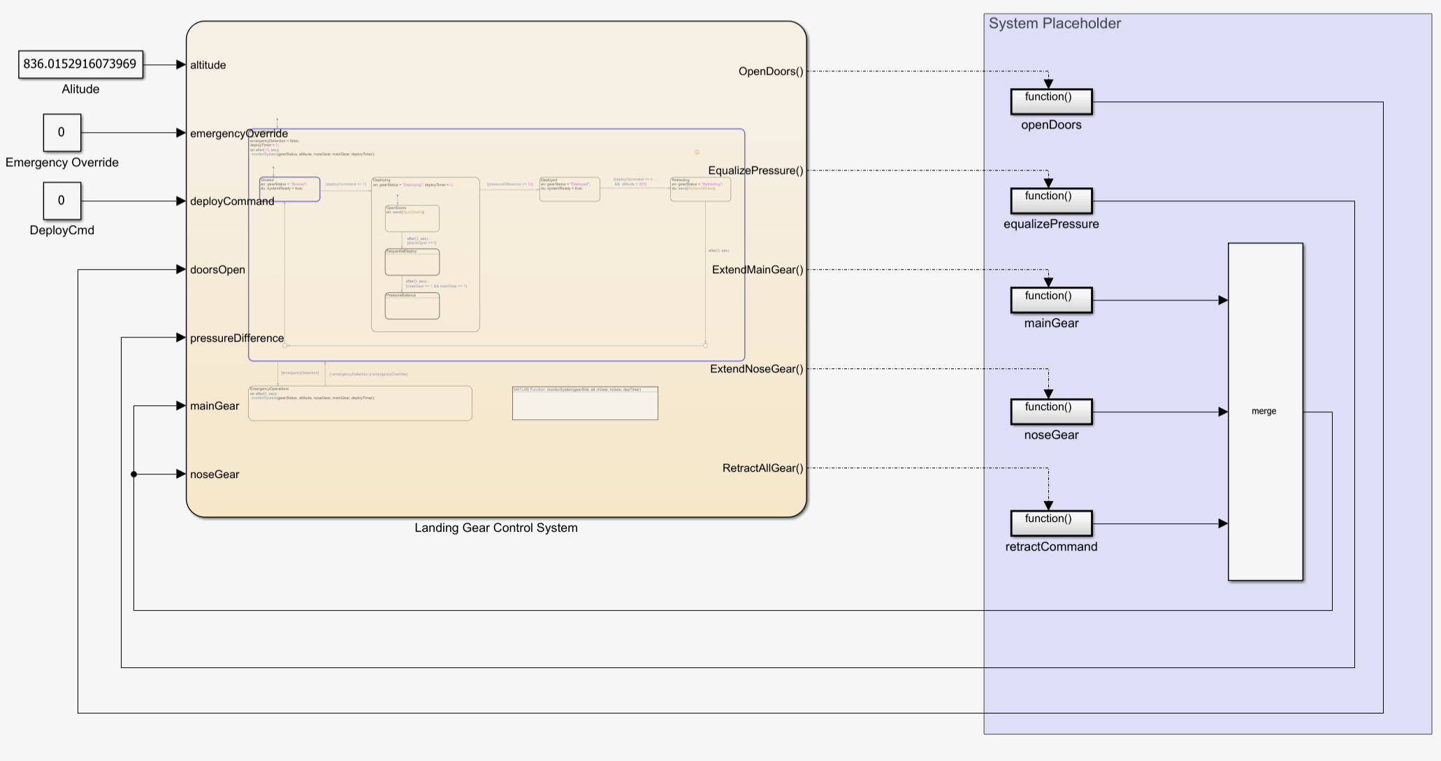
Hydraulic landing gear systems require control logic that manages the order and timing of actuator operations. Open the sfHydraulicActuator model. This model contains:
Signals for deployment commands, altitude, emergency mode status, and gear position feedback
A Stateflow chart that implements the control logic
Five function-call subsystems that model hydraulic operations
Signals to display gear status and system readiness
The chart implements mode-based scheduling at the top level, and switches between four operational modes: Stowed, Deploying, Deployed, and Retracting. In the Deploying state, the chart uses event-driven ladder logic to respond to sensor feedback and coordinate sequential gear extension.
During simulation, the Landing Gear Control System chart extends the gear assemblies in sequence to prevent interference and maintain aerodynamic stability. After extension, the chart equalizes hydraulic pressure across multiple actuators to prevent uneven loading. Throughout operation, the chart monitors the system for emergencies.
The Landing Gear Control System chart also coordinates six function-call subsystems in the System Placeholder area. The chart broadcasts function-call events that trigger subsystem execution based on the current operating mode and system conditions.
The function-call subsystems in the System Placeholder area execute at discrete rates triggered by the Stateflow chart. The chart broadcasts function-call events that activate subsystems based on the current mode and system conditions.
Examine the Instrument Dashboard Panel
The Instrument Dashboard panel uses Dashboard blocks to simulate the controls a pilot uses on their instrument dashboard.
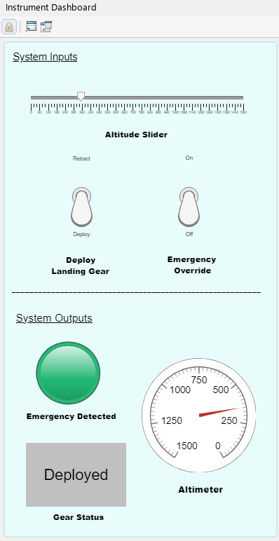
The upper half of the Instrument Dashboard panel contains Dashboard blocks that control the system inputs. You can use the slider to adjust the altimeter and toggle switches to deploy the landing gear or override an emergency situation.
The lower half of the Instrument Dashboard panel contains Dashboard blocks that show the system outputs. The light turns red if the system detects an emergency situation, the altimeter displays the current altitude setting, and the gear status displays the current state of the landing gear.
Examine the Landing Gear Control System Chart
The chart implements mode-based scheduling with four operational modes that correspond to landing gear states: Stowed, Deploying, Deployed, and Retracting. In the Stowed state, the gear is retracted, and the chart waits for a deployment command. In the Deploying state, the chart opens the gear bay doors, extends the three gear assemblies by using ladder logic, and equalizes hydraulic pressure by using loop logic. In the Deployed state, the chart extends and locks the landing gear. In the Retracting state, the chart retracts all gear assemblies.
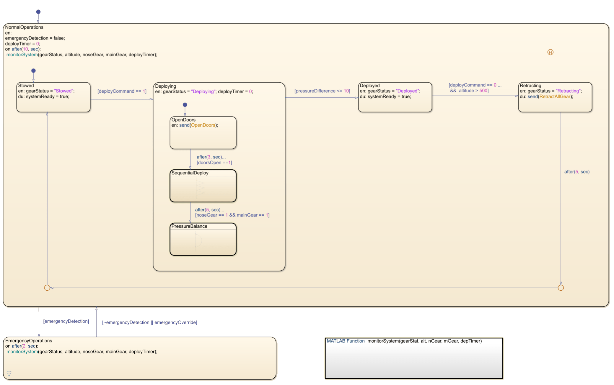
The Stowed and Deployed states are stable states where the chart waits for external commands. The Deploying and Retracting states are active control phases where the chart coordinates subsystem execution.
The chart continuously monitors the system for any abnormalities with the MATLAB function, monitorSystem. If the chart detects an issue, the chart immediately transitions to the EmergencyOperations state. The EmergencyOperations state demonstrates fault management within the scheduling framework. The chart monitors system health and can interrupt normal mode-based execution to handle emergencies, which ensures safe operation under abnormal conditions.
Examine the Temporal Logic in the Deploying State
The Deploying state uses temporal logic to control when the tasks for landing gear deployment occur. The chart switches between three exclusive substates, OpenDoors, SequentialDeploy, and PressureBalance. OpenDoors is the default substate, and it becomes active first. Each subsequent substate waits for a specific time before starting, to allow for each task to complete.
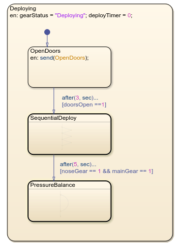
The chart uses the temporal logic operator after to control this delay. The transition from the OpenDoors substate to the SequentialDelay substate is guarded by after(3, sec). This operator prevents the transition until OpenDoors becomes active and three seconds have passed. Similarly, the transition between SequentialDeploy and PressureBalance is guarded by after(5, sec). This transition can only occur after SequentialDeploy becomes active and five seconds have passed .
For more information about temporal operators, see Control Chart Execution by Using Temporal Logic.
Examine the Ladder Logic in the SequentialDeploy State
The SequentialDeploy state uses ladder logic to extend the three landing gear assemblies in sequence. The chart checks the altitude, extends the main gear, waits for position confirmation, then extends the nose gear.
In Stateflow, you use flow charts with with conditional transitions and junctions to create ladder logic. Each condition checks whether the previous step completed before proceeding to the next step. The SequentialDeploy substate flow chart contains three steps:
If the transition guard
[altitude < 15000 && ~noseGear]istrue, then the chart executes the{send(ExtendNoseGear);}action.If the transition guard
[noseGear == 1]istrue, then the chart executes the{send(ExtendMainGearLeft);}action.If the transition guard
[mainGearLeft == 1]istrue, then the chart executes the{send(ExtendMainGearRight);}action.
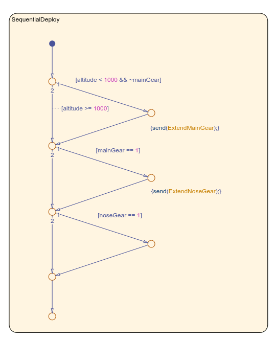
The chart evaluates each condition in order. When a condition is true, the chart broadcasts an event to the corresponding function-call subsystem. The subsystem executes and returns the control signal to the chart. The chart then evaluates the next condition. If a condition is false, the flow chart exits and re-evaluates the condition on the next time step.
Examine the Loop Logic in the PressureBalance State
The PressureBalance state uses loop logic to equalize the hydraulic pressure across the three landing gear actuators. The chart executes the EqualizePressure subsystem until the pressure differential is in a defined tolerance.
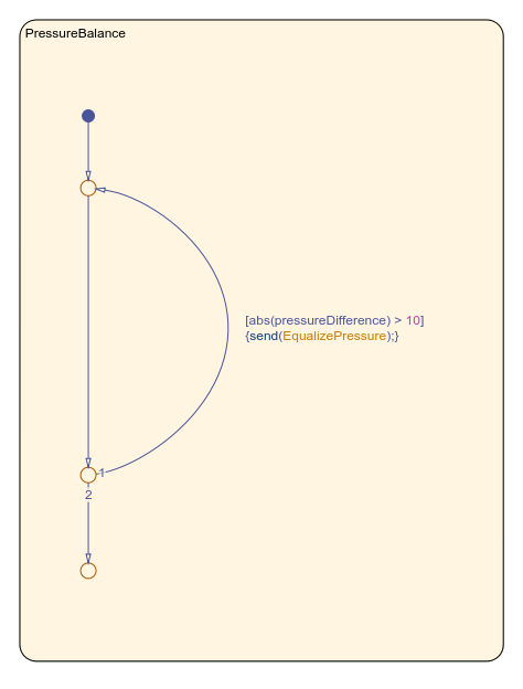
The flow chart in the PressureBalance state checks if the difference in pressure difference is greater than 10. When true, the chart broadcasts the EqualizePressure event and increments the counter. The transition creates a self-loop back to the same junction. When difference is less than or equal to 10, the chart exits the flow chart.